Technical
Deep Well Level Transmitters: Probes for 2-Inch Boreholes Up to 500 m
Compare small-diameter probes, submersible cables, and lightning protection for deep well level transmitters to 500 m. Send your well specs for a free recommendation.
Compare small-diameter probes, submersible cables, and lightning protection for deep well level transmitters to 500 m. Send your well specs for a free recommendation.
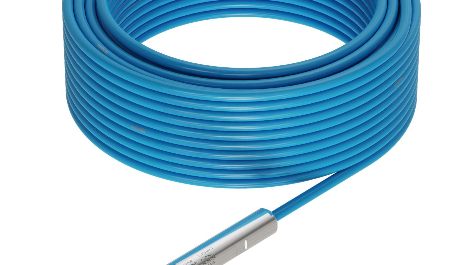
A deep well level transmitter is a submersible hydrostatic instrument that measures liquid level or groundwater depth in wells, boreholes, and reservoirs by converting hydrostatic pressure into a standardized process signal such as 4-20 mA, RS-485 Modbus, or HART. Deep well models cover ranges up to 500 m with typical 0.5% FS accuracy (0.25% FS available), and narrow-borehole variants use probes as small as 16 mm in diameter to pass through 2-inch wells. WELK manufactures small-diameter borehole level transmitters, deep well level transmitters, and armored-cable submersible transmitters engineered for this duty class.
A tank is a contained, accessible vessel. A well is a narrow, deep, often unlined hole in the ground. The differences change almost every design decision.
Physical access. A 2-inch borehole has an inside diameter of roughly 50.8 mm, yet it must accommodate the probe, the cable, and sometimes a drop pipe for pumping. This drives the demand for small-diameter probes in the 16-22 mm range. A standard 27 mm tank probe simply will not fit. Even in a 4-inch borehole (about 100 mm ID), the probe must pass couplings, screen sections, and potential deviations in the casing without snagging.
Depth and cable length. Tank level transmitters rarely exceed a few meters of submersion. Deep wells run from tens to hundreds of meters. A 300 m well demands a 300 m cable, and cable selection — vented, armored, signal-compatible — becomes a structural decision, not an accessory. Cable resistance, capacitance, and tensile strength all matter at that length.
Measurement principle constraints. Radar and ultrasonic level sensors, which work well on tanks, are often impractical in wells. Guided-wave radar requires a probe rod or cable long enough to span the full measuring range, which is expensive and physically difficult to install in a deep, narrow borehole. Non-contact radar cannot see a target reliably through the top of a small-diameter casing, and ultrasonic sensors lose accuracy over long ranges and in the humid, turbulent air column of a well. Hydrostatic submersible transmitters are unaffected by foam, vapor, condensation, or depth — which is why they dominate this application. For adjacent duties in lift stations and reservoirs, see WELK's water and wastewater level measurement guide.
Environmental severity. Wells are subject to groundwater chemistry, silt, biofouling, and in remote sites, lightning-induced transients on long cable runs. A tank transmitter bolted to a nozzle does not face a 300 m cable acting as an antenna during a storm. These environmental factors drive the need for robust housings, IP68 sealing, vent tube protection, and surge suppression.
A hydrostatic level transmitter measures the pressure head of the liquid column above its diaphragm. The governing relationship is:
P = ρ × g × h
Where P is hydrostatic pressure in pascals, ρ is the liquid density in kg/m³, g is gravitational acceleration (9.81 m/s²), and h is the liquid height in meters. Rearranged, the measured height is h = P / (ρ × g).
Because the transducer is sensitive to total pressure — liquid head plus atmospheric pressure on the surface — the transmitter must subtract the atmospheric component. This is why submersible probes use a vented cable with a built-in capillary tube that carries a reference pressure from a vented connector at the surface down to the back of the sensor diaphragm. The atmospheric reference cancels barometric drift, so the output reflects only the liquid column height. A sealed (non-vented) gauge sensor drifts with every weather change and should not be used for well level monitoring.
Density is the other term that matters. A probe calibrated for water (1,000 kg/m³) will read 20% low in a 1,200 kg/m³ brine and 5% high in a 950 kg/m³ process fluid. For wells, the medium is usually groundwater, so water calibration is standard — but if the well carries brine, leachate, or a contaminated groundwater plume, the actual density must be entered into the calculation or the transmitter must be factory-calibrated for that fluid. WELK's submersible hydrostatic level transmitter is available with custom density calibration and a range of diaphragm materials for corrosive groundwater.
The single most important dimension is the outer diameter of the probe relative to the smallest restriction in the well — usually the casing, a well screen, or a threaded coupling. As a rule of thumb:
Clearance is not optional. A probe that fits the casing on paper can still jam on a misaligned joint, a mineral deposit, or a slight bend in the casing. Specifying the largest probe that still clears every restriction maximizes diaphragm area, which improves accuracy and reduces clogging sensitivity.
A floating or drifting probe produces false level readings. Every submersible well transmitter should be fitted with a stainless steel bottom weight — typically 316L stainless, from roughly 0.5 kg for shallow wells up to 2-3 kg for deep or flowing wells — to keep the probe anchored at the correct measuring depth. The weight also keeps the cable under tension so it does not coil and abrade against the casing. On deep well level transmitter configurations, WELK rates the suspension point for the full probe-and-weight assembly so the cable never carries the load of a heavy weight alone.
Cable choice is a reliability decision, and for wells it should be made at the specification stage:
Keep in mind that the vented capillary is the probe's "breathing" system. If it fills with water, the atmospheric reference is lost and readings drift. The cable termination at the surface must be kept above potential flood levels and fitted with a desiccant — this point is revisited under installation.
The mechanical cable length and the electronic measuring range are often the same number in a well, but they are not the same specification. A 200 m well needs a 200 m cable; the transmitter range should be the maximum expected water column above the probe, not the full well depth. If the probe is suspended 5 m below the expected minimum water level, a 200 m range transmitter measures the 195 m of head between the probe and the maximum level. Overspecifying the range reduces resolution and accuracy, so match the range to the actual liquid column — then confirm the cable can reach the lowest installation point with margin.
Long cable runs add resistance and capacitance that can degrade signals:
A long vertical cable from a probe deep in the ground to a controller at the surface is effectively a lightning antenna. Even without a direct strike, nearby strikes induce kilovolt surges on the cable, which destroy unprotected transmitters at the diaphragm and the input stage of the PLC or RTU. Protection is mandatory, not optional:
The same basic probe is deployed in two very different regimes:
Groundwater monitoring is typically remote, battery- or solar-powered, and low-bandwidth. Level data is logged by a data logger and polled over telemetry — LoRa, NB-IoT, GPRS/4G, or satellite — at intervals from minutes to days. Power budget is the dominant constraint, so the transmitter must be a low-power loop or a 3.3-5 V digital sensor, and the cable must be rated for permanent submersion without maintenance access. Accuracy of 0.5% FS is usually sufficient for aquifer trend analysis; long-term zero stability and battery life matter more than resolution.
Industrial tank duty is powered continuously, has a control system nearby, and often demands loop-powered 4-20 mA with HART diagnostics, higher accuracy (0.25% FS), and materials matched to the process. The wellhead or borehole in a plant (e.g., an extraction well feeding a treatment train) is a hybrid: it needs the well-form-factor probe but the industrial output protocol.
Before specifying, work through WELK's RFQ checklist for hydrostatic level transmitters — it covers the questions (density, range, cable length, media chemistry, and power) that decide between a groundwater monitoring probe and an industrial tank transmitter.
| Application | Probe diameter | Typical range | Accuracy | Output | Cable | Best for |
|---|---|---|---|---|---|---|
| 2-inch borehole | 16-22 mm | 0-10 m to 0-100 m | 0.5% FS | 4-20 mA / RS-485 | Vented PUR; small dia. | Groundwater monitoring; piezometers; shallow wells |
| 4-inch borehole | 22-27 mm | 0-30 m to 0-200 m | 0.5% FS | 4-20 mA / RS-485 / HART | Vented PUR or armored | Monitoring wells; dewatering wells |
| Deep well (100-500 m) | 22-27 mm | 0-200 m to 0-500 m | 0.25-0.5% FS | 4-20 mA / HART | Armored vented; strength member | Water supply wells; mine dewatering |
| Open reservoir | 27 mm+ | 0-5 m to 0-100 m | 0.5% FS | 4-20 mA / RS-485 | Standard vented | Reservoir and pond level; water storage |
| Groundwater network | 16-22 mm | 0-10 m to 0-100 m | 0.5% FS | RS-485 / SDI-12; low power | Vented PUR | Multi-point aquifer monitoring; telemetry |
For a deeper comparison across sensor technologies for water and wastewater service, including when a well probe beats a radar or ultrasonic unit, see WELK's water and wastewater level measurement sensor selection guide. If your well feeds a reservoir or storage basin rather than a process line, the wells and reservoirs application page walks through the full measurement chain.
Suspension method. Lower the probe on the vented cable itself only when the cable is rated for suspension and fitted with a strength member. For deep wells, a separate stainless steel hanger wire or Kevlar cord takes the mechanical load, and the electrical cable is lashed to it at intervals of 1-3 m. This prevents cable stretch and connector strain over a 200 m drop.
Bottom weight. Attach a 316L stainless weight sized to the flow conditions — light for still groundwater, heavier for wells with active pumping drawdown where inflow could lift the probe. Confirm the measuring zero reference: the diaphragm sits at a fixed offset above the weight tip, so record this offset during commissioning for accurate depth-to-water calculations.
Avoid the silt line. Suspended sediment and collapsed well material accumulate on the well bottom. Hanging the probe at the deepest possible point but at least 0.5-1 m above the expected sediment level protects the diaphragm from burial and clogging, while the intake gap between the diaphragm and the sediment remains clear.
Vent tube discipline. The vented cable termination must be in a dry, elevated enclosure with a desiccant cartridge. If the vent cap is flooded or the desiccant is saturated, water wicks down the capillary and the atmospheric reference is lost — the classic "slow drift over weeks" failure. Replace desiccants on a maintenance schedule, typically every 3-6 months in humid climates.
Wet the sensor before signal checks. A hydrostatic probe cannot be verified in air. Commission with the probe immersed at a known depth, or use a certified deadweight/pressure tester on the diaphragm. Verify the 4 mA point at zero head and the span with a known water column, then log the as-installed zero.
Submersible probes in wells fail predictably, and most failures are preventable:
A practical maintenance plan is to retrieve, clean, inspect, and recalibrate well transmitters every 12-24 months depending on water chemistry and fouling history. Document each retrieval so drift trends are visible before they become process errors.
What is the difference between a deep well level transmitter and a borehole level transmitter? They operate on the same hydrostatic principle; the distinction is form factor and rating. A borehole level transmitter is the small-diameter variant (16-22 mm) sized for 2-inch and 4-inch monitoring wells, typically with a 10-100 m range. A deep well level transmitter is built for ranges up to 500 m, with longer armored vented cables, heavier suspension ratings, and usually surge protection for the longer cable run.
Can a 4-20 mA level transmitter work in a 300 m well? Yes. The 4-20 mA current loop is immune to voltage drop along the cable, so a properly supplied loop carries a reliable signal for hundreds of meters. Confirm the supply voltage stays above the transmitter's minimum (about 9 V DC) at the far end and that the total loop resistance — cable plus any indicators — is within the 4-20 mA / HART budget.
How do I protect a well level transmitter from lightning strikes? Use three layers: an integral surge protection module on the transmitter itself, a line surge protective device (SPD) at the controller end of the 4-20 mA or RS-485 cable, and correct single-point grounding with low-impedance earth (typically under 4 Ω). Ground the cable shield at one defined point to avoid ground loops.
Why does my submersible probe reading drift slowly over time? The most common cause is water entering the vent tube through a flooded or compromised vent termination, which destroys the atmospheric reference. Check and dry the vent cap, replace the desiccant, and inspect the cable for cuts. If drift continues, the sensor diaphragm may be fouled or the gauge cell may need recalibration.
How deep can a submersible hydrostatic level transmitter measure? Standard WELK deep well transmitters cover ranges up to 500 m (custom ranges available), with 0.25-0.5% FS accuracy. The practical limit is cable length and installation mechanics rather than the pressure sensor itself, which is why cable armor and suspension rating are specified together with the range.
Selecting the right deep well level transmitter comes down to four numbers: well depth, borehole diameter, expected water column, and media chemistry. Send those four values to WELK's engineers at sales@level-meters.com or through the inquiry form, and receive a free recommendation for the correct probe diameter, range, output protocol, cable type, and surge protection — with pricing for your exact well configuration. For specifications on the products discussed here, visit the deep well level transmitter product page or review WELK's factory and quality control processes before you buy.
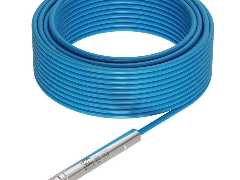
Submersible deep-well level transmitter with long cable, IP68 probe and output selected for groundwater or reservoir monitoring.
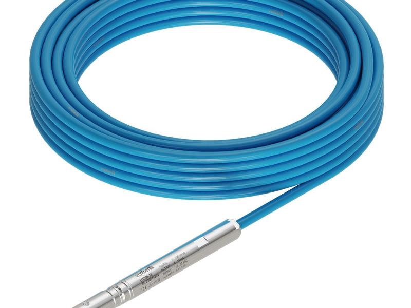
Small-diameter hydrostatic level transmitter for narrow boreholes, monitoring tubes and restricted-access wells.
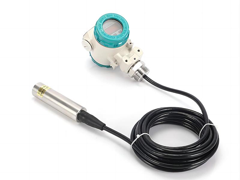
Submersible hydrostatic level transmitter for wells, reservoirs, tanks and water projects with cable length and output configured by depth.
Send drawings, dimensions, material, environment or operating conditions, and we will help confirm the right specification.
Uploaded reference files are included with the inquiry. For larger CAD packages, reply to the confirmation email or send them here:
Our team typically replies within 24 hours.