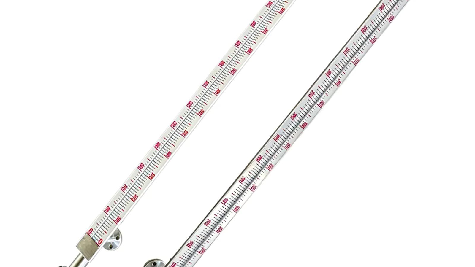
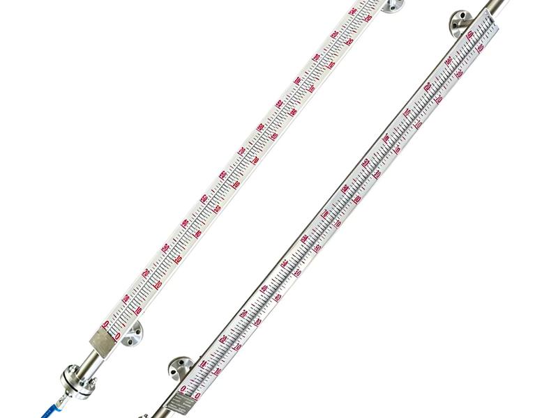
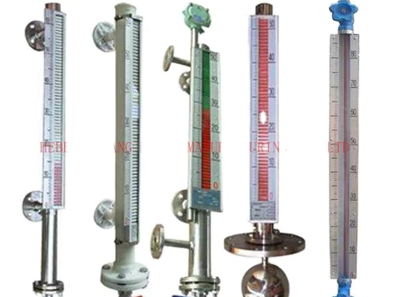
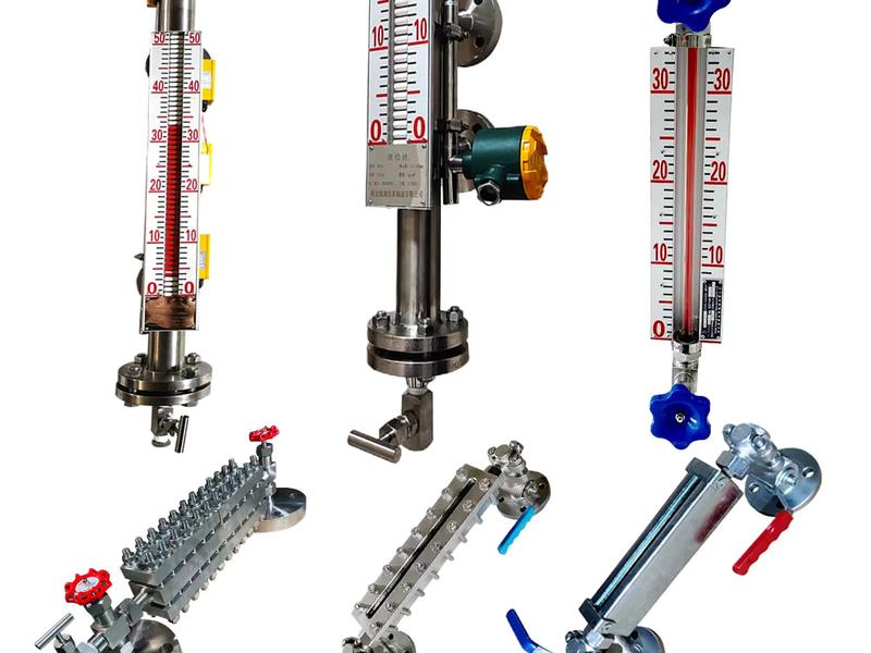
A high-pressure and high-temperature magnetic level gauge is a non-contact visual level instrument built around a pressure-rated chamber — normally a 316L stainless-steel or nickel-alloy tube connected to the vessel through ASME B16.5 flanges in classes from Class 150 up to Class 900 — that contains a sealed internal float whose permanent magnets flip an external row of flag indicators as the liquid level rises and falls. Unlike a standard magnetic level gauge sized for atmospheric or low-pressure duty, the high-pressure/high-temperature version is engineered for design pressures up to 16 MPa (160 bar) and process temperatures from roughly −40°C to +450°C, with the float rated to a collapse pressure that leaves a defined safety margin above maximum working pressure and the chamber, flanges and gaskets certified to codes such as ASME B16.5, EN 1092-1 or GB/T standards. These instruments are specified on boiler drums, steam drums, ammonia converters, chemical reactors and thermal-fluid systems, where a conventional glass sight gauge would be a hazard and engineers still need reliable local visual indication when the process is hot, pressurized, or exposed to freezing ambient conditions.
Why Standard Magnetic Level Gauges Fail at High Pressure and High Temperature
Standard magnetic level gauges fail in severe service for a few well-documented reasons, and understanding them is the first step in specifying a unit that will survive a decade in a boiler house.
Flange and gasket failure. At pressures above roughly 4–6 MPa, ordinary rubber or PTFE gaskets cold-flow and extrude under bolt load, and lightweight flanges deflect. The result is weeping at the flange faces, progressive gasket erosion, and eventually a leak of superheated water or process vapor. High-pressure gauges use thicker, reinforced flanges (Class 600 and above), spiral-wound or graphite gaskets, and stud bolts torqued to a defined pattern.
Float collapse. The float is the single most failure-prone component. A hollow float designed for 1 MPa can be crushed — collapsed and internally flooded — when the chamber is pressurized to 10 MPa. Once the float floods, it sinks, the magnetic flags stop tracking the surface, and the gauge reads wrong or not at all. High-pressure floats are machined from solid bar or welded from thick wall tube, and their collapse pressure is verified by hydrostatic test to a margin of at least 1.5 times the maximum working pressure.
Magnet degradation. Above roughly 250–300°C, ordinary ferrite and many AlNiCo magnets lose a significant fraction of their magnetic flux. If the float magnet and the indicator magnets are not rated for the operating temperature, flag tracking becomes sluggish and unreliable — flags may stick, partially flip, or flip back. High-temperature gauges use samarium-cobalt (SmCo) or high-grade AlNiCo magnets with Curie points well above 450°C.
Differential expansion and thermal cycling. A chamber heated from ambient to 400°C grows by millimetres in length. If the mounting feet, brackets and flanges cannot accommodate that growth, the chamber distorts, the float binds against the wall, and the gauge fails mechanically. Proper designs anchor the chamber at one end and allow free axial movement at the other.
Sticking and coating. Viscous, crystallizing or polymerizing media can build up inside the chamber and on the float. In hot service, minor boiling at the surface can cause bubble entrainment that makes the float bob. These issues are addressed by chamber design, by steam jacketing (discussed below), and by specifying the correct process connection.
Design Pressure Ratings and Flange Classes for High-Pressure Service
Specifying a magnetic level gauge for high-pressure service is fundamentally a flange-and-chamber rating exercise. The design pressure and temperature define the flange class, the chamber wall thickness, and the gasket material.
The common rating ladder for WELK high-pressure magnetic level gauges follows both the European PN series and the ANSI/ASME class series:
| Flange rating | Nominal design pressure | Typical service |
|---|
| PN16 / Class 150 | 1.6 MPa / 2 MPa at 20°C | Steam headers; condensate; general chemical |
| PN25–PN40 / Class 300 | 2.5–4.0 MPa | Boiler feedwater; thermal oil |
| PN63–PN100 / Class 600 | 6.3–10 MPa | Boiler drums; ammonia synthesis; reactors |
| PN160 / Class 900 | 16 MPa / 15.9 MPa | High-pressure boiler drums; HP hydrogen service |
Note that flange ratings are temperature-derated. A Class 900 flange is rated for roughly 15.9 MPa at 38°C, but its allowable pressure drops as temperature rises; at 400°C the same flange is good for a lower value, and the chamber wall thickness is calculated accordingly. This is why the design pressure and the design temperature must always be specified together — never pressure alone.
For boiler drum level measurement in particular, drums operate typically between 4 and 12 MPa with saturated temperatures from 250°C to 320°C, while high-pressure drums in large utility boilers can reach 15–16 MPa. The chamber is usually made from seamless tube or forged bar, radiographed, and hydrostatically tested to 1.5× the design pressure. Flange faces should be specified by facing standard (RF, RTJ for the highest classes), and the bolt torque sequence must be defined in the installation manual. The vent valve on top and drain valve below complete the pressure boundary — both should be rated to full design pressure, since they are often the first components to leak if undersized.
Chamber and Float Materials for High-Temperature Service
Material selection is what separates a gauge that lasts from one that corrodes, scales, or fails in months. At high temperature, three factors drive the choice: corrosion resistance, creep and oxidation resistance, and the float's mechanical strength.
Chamber materials. The default is 316L stainless steel, which is suitable for the majority of steam, water, thermal-fluid and general chemical services up to 450°C. Where the process is more aggressive — chlorides, sulphuric or hydrochloric acid, high-chloride steam — the chamber should be upgraded to a higher alloy:
- 904L — better resistance to chlorides and reducing acids.
- Duplex 2205 or super-duplex 2507 — high strength, excellent chloride-stress corrosion cracking resistance, popular for offshore and brine service.
- Hastelloy C-276 or Inconel 625 — for hot chlorides, wet chlorine, and oxidizing media.
- Monel 400 — for hot fluoride and hydrofluoric acid service.
The chamber wall thickness is calculated to the applicable design code, and for alloy chambers, weld procedure qualification (WPQ) records should be requested. The internal surface finish matters too: a smoother bore (Ra ≤ 0.8 µm) reduces fouling and float drag, which matters in viscous hot media.
Float material and collapse pressure. The float is the critical component. For high-pressure, high-temperature service, floats are fabricated from thick-walled tube, welded and X-rayed, or machined from solid bar, so that wall thickness can be much greater than a thin-sheet float. A float rated for 16 MPa service will typically have a tested collapse pressure above 24 MPa (1.5× design). The float material should match the corrosion resistance of the chamber — 316L for general service, Inconel or Hastelloy for aggressive media, and titanium where the process demands it.
Because a float is hollow, its density is much lower than solid metal, which is what allows it to float on the liquid surface. The lower the float density, the better it tracks low-density liquids, but a lower density also means thinner walls — so there is always a trade-off between buoyancy and collapse pressure. High-pressure floats are inherently denser, which is why a high-pressure magnetic level gauge may have a slightly larger dead band (the distance between the highest and lowest detectable level) than a low-pressure unit. Always check the float collapse pressure against the maximum working pressure and the fluid density against the float's effective density.
Seals and gaskets. For high temperature, elastomeric gaskets are replaced by spiral-wound gaskets with graphite fill, or solid graphite gaskets, which are good to 450°C and above. Valve packing in the vent and drain valves should be graphite or PTFE with a suitable temperature rating. O-rings on the indicator side are generally not in the pressure boundary, but the flag indicator housing should still be specified for the ambient conditions it will face.
Steam Jackets: How They Work and When to Use Them
A steam-jacketed magnetic level gauge is a high-pressure magnetic level gauge in which the level chamber is enclosed in a second, outer jacket through which low-pressure steam circulates. The jacket keeps the process liquid inside the chamber at a stable temperature, preventing the liquid from freezing, from becoming so viscous it stops the float moving, or from crystallizing and coating the chamber wall.
How the jacket works. The outer jacket is welded around the level chamber with a small annular gap (typically 10–20 mm). Saturated steam at 0.3–0.6 MPa (3–6 bar) — roughly 145–165°C — is admitted at the lower connection and leaves at the upper connection, so that condensate drains out by gravity and the jacket fills uniformly with steam. Jacket connections are usually G1/2" or DN15, and the steam supply is typically taken from the plant's low-pressure steam or traced-service header. On some designs the jacket is also used to circulate hot water or thermal oil where steam is not available.
When to use a steam jacket. A jacket is justified when the process liquid itself would otherwise be the problem:
- Viscous or waxy media — bitumen, heavy fuel oil, tar, sulphur, naphthalene. Above roughly 5–20 cSt at ambient temperature, the float stops moving reliably. A jacket holds the liquid at its pumping temperature.
- Crystallizing media — caustic soda, sodium salts, urea solutions, sulphur. When the liquid cools below its crystallization point, solids deposit on the chamber wall and freeze the float.
- Media that must not be allowed to freeze — thermal oil, ammonia, caustic, water in cold climates.
The key rule is that the jacket temperature must be controlled, not just supplied. Oversupplying steam to a jacket on a heat-sensitive medium can overheat or boil the product; use a thermostatic trap and, if necessary, a pressure-reducing valve on the steam supply to hold the jacket at a set pressure. The steam trap is part of the system, not an accessory — an unchecked trap allows the jacket to flood with condensate and lose most of its heating effect.
Insulation. A steam jacket that is not insulated defeats much of its purpose in freezing conditions. Mineral-wool or rock-wool insulation, 50–80 mm thick with a weatherproof cladding, should be fitted over the jacket. If the jacket is only needed to keep the liquid above its pour point, a jacket-plus-insulation combination is the standard package — WELK's steam-jacket magnetic level gauge is supplied with the jacket as an integral part of the chamber assembly, so the pressure boundary and the heating envelope are designed and tested as one unit rather than bolted together on site.
Frost Protection and Heat Tracing for Outdoor Installations
Where a steam jacket is about keeping the process liquid hot, frost protection is about keeping the gauge operational in cold ambient conditions. Outdoor installations — tank farms, chemical plants, refineries, LNG and ammonia terminals, boiler yards in cold climates — routinely see ambient temperatures below −20°C and in design conditions down to −40°C. Water and condensate inside a chamber will freeze, expand, and crack the chamber or the float; even where the process liquid is non-freezing, the indicator and the liquid inside the chamber can condense and freeze.
There are three complementary measures:
1. Heat tracing. The most common approach is electric heat tracing — a self-regulating heating cable run along the chamber and wrapped around the flanges and the float travel zone, protected by the insulation and cladding. Self-regulating cable (typically 15–30 W/m) is preferred over constant-wattage cable because it adjusts its output to the local temperature, cannot overheat the process, and can be cut to length on site. The trace is controlled by a thermostat or an ambient-temperature controller, and it must be laid in full contact with the chamber surface — a trace that is floating in the insulation heats nothing but the air.
2. Insulation and cladding. Insulation holds in the heat, whether from the trace or from the process itself. For a frost-protected gauge, 50–100 mm of insulation with a removable cladding or a hinged box is typical. The cladding must be removable around the flanges and the indicator so that inspection and maintenance are not compromised.
3. Steam tracing or jacket. Where steam is available on site, a low-pressure steam jacket at 0.3–0.6 MPa provides the same protection as an electric trace without a power supply and is intrinsically explosion-safe. For very cold duty, a jacket is often combined with insulation; the jacket keeps the liquid warm while the insulation reduces the heat loss.
The design condition for frost protection is the minimum ambient temperature — for most Chinese and northern-hemisphere specifications this is −20°C, with −40°C used for severe cold regions. This is also why the float and indicator must be rated for the low-temperature ambient: at −40°C, materials must not become brittle, and the indicator housing should be sealed against ice ingress. WELK's insulated frost-proof magnetic level gauge is built specifically for this duty, with the insulation, cladding, and trace (or steam jacket) integrated into a single engineered package rather than assembled in the field.
Condensation and Indicator Flag Reliability
The flag indicator is the part of the gauge the operator actually reads, and it is also the part most likely to fail in humid, cold, or outdoor environments. Condensation forms inside the indicator housing when warm humid air enters the housing and then cools — a frequent failure mode on outdoor gauges in spring and autumn, and on gauges near steam leaks. Condensation fogs the window, corrodes the indicator springs and axle pins, and can freeze in winter, locking the flags in position.
Three design features keep the indicator reliable:
- A sealed or gas-filled indicator housing. A properly gasketed, IP65–IP66 indicator housing prevents humid air from entering in the first place. On cold outdoor duty, some designs add a small desiccant cartridge or a silica-gel breather.
- Non-magnetic, corrosion-resistant internal parts. Flag axles and springs should be stainless steel or a corrosion-resistant alloy, not carbon steel, so that minor condensation does not seize the mechanism.
- High-coercivity indicator magnets. The flags are flipped by the float's magnet through the chamber wall. The magnets must be strong enough to operate through a thicker, high-pressure chamber wall, and must be rated for the temperature so that tracking is positive — a partially flipped flag is a false reading.
The indicator magnet and float magnet must also be sized so that the coupling force is sufficient over the full temperature range. As the float magnet's temperature rises, its flux drops; a gauge specified for 350°C service will have a larger magnet or a higher-grade material than the same gauge specified for 100°C. For critical boiler drum level measurement, where the gauge is one of several redundant instruments, operators should verify flag tracking during commissioning at operating temperature — flags should flip cleanly with no halfway positions.
Magnetostrictive Transmitter Retrofit for Remote 4–20 mA Output
A visual flag indicator is the operator's primary check, but modern DCS and PLC control requires a remote analog signal. On a high-pressure magnetic level gauge, the standard retrofit is a magnetostrictive level transmitter: a guided wave probe — a slim tube or rod — is inserted into the chamber from the top or the side, and the float carries a magnetic ring that the transmitter tracks magnetostrictively.
The principle is simple and robust. A current pulse is launched down the magnetostrictive wire, generating a torsional strain wave at the position of the float's magnetic ring; the transmitter measures the time of flight and converts it to an accurate level. Because the measurement is digital time-of-flight, it is highly repeatable — typically ±1 mm — and unaffected by pressure, temperature, foam, or dielectric changes. The output is a standard two-wire 4–20 mA HART signal, which connects directly to any PLC, DCS, or SCADA input.
The retrofit is particularly attractive on high-pressure gauges because it adds a continuous electronic signal without cutting new nozzles into the vessel or breaking the pressure boundary more than necessary. The probe passes through a flange and a small chamber opening, and the whole assembly is rated to the same design pressure as the gauge. For boiler drums and ammonia service, the probe insertion point should be chosen so the float travel is not obstructed, and the transmitter housing should be rated for the ambient conditions — explosion-proof housings are available for hazardous areas.
WELK supplies the high-pressure gauge with an integrated magnetostrictive transmitter, or as a magnetic level gauge switch transmitter package that combines the visual indicator, up to several limit switches (for alarms and pump interlock at high/high-low/low points), and the continuous 4–20 mA transmitter in a single instrument. This gives operators the visual reading, the trip contacts, and the analog signal from one field device, all rated for the same design pressure.
Installation, Venting and Calibration
Correct installation determines whether the gauge performs to its data sheet. The critical points are the process connections, the venting, and the alignment.
Process connections. For side-mounted high-pressure gauges, the chamber is connected to the vessel through the two flanges or threaded nozzles, with isolation valves on each connection so the gauge can be isolated and removed for maintenance without dropping the vessel. For top-mounted versions, the probe is inserted through the top nozzle. The chamber must be installed close to vertical — a lean of more than a degree or two creates an offset between the true level and the indicated level, and on a long chamber the accumulated error is significant. On boilers and steam drums, the water-level connections must be taken from the drum's dedicated level connection points, and the gauge installed so that the lower connection sees the true water space and the upper connection the steam space.
Venting. The chamber must be vented at the top connection. If the chamber is not vented, trapped air or steam accumulates at the top, the liquid surface inside the chamber sits higher than the vessel surface, and the gauge reads high — a potentially dangerous error on a boiler drum. The vent valve is also used to purge air during commissioning. On steam service, the gauge must be operated with the steam-side connection draining condensate correctly, or the chamber fills with condensate and reads false.
Calibration. A magnetic level gauge is calibrated by geometry: the zero corresponds to the lower tap, the span to the distance between the taps. On a boiler drum, zero/span must be corrected for the actual drum tap spacing and for the water column density at operating temperature and pressure — this is the "cold calibration vs hot calibration" correction that boiler operators are familiar with. With a magnetostrictive transmitter, the zero and span points are set electronically after installation and should be verified against the visual flags at a known mid-level before the vessel is pressurized, and re-checked at operating temperature.
For a side-mounted gauge, note that the measured range is the distance between the two tap centers, not the full chamber length. The float's dead band means the lowest and highest measurable points sit slightly inside the taps, and the indicator scale should be marked accordingly.
Maintenance and Inspection: Float Collapse and Gasket Replacement
Preventive maintenance on a high-pressure magnetic level gauge is straightforward, but it must be scheduled — these instruments are safety-related on boilers and reactors.
Float inspection. The float is the wear component. Every time the gauge is isolated, the float should be removed, dried, and weighed against its marked empty weight. A float that has taken on liquid — through a pin-hole weld, a cracked seam, or a collapsed end — weighs more and floats lower, producing a false low-level reading. Any float showing a weight gain must be replaced. The float should also be checked for collapse: on a high-pressure gauge, a collapsed float is often first detected by a sudden loss of buoyancy and a gauge that reads "full" regardless of actual level. If there is any doubt about the float's condition, pressure-test it in the chamber or return it to the factory for hydrostatic re-verification.
Gasket replacement. Flange gaskets on high-pressure service should be replaced on a defined schedule or whenever the flanges are broken. Spiral-wound gaskets are one-use: once the joint has been opened, fit a new gasket, torque the studs in the prescribed sequence and to the specified values, and record the torque. Graphite gaskets should never be reused. Check the flange faces for damage, corrosion or "orange peel" — a damaged face will leak no matter how good the gasket is.
Bolt torque. The vent and drain valves, and the chamber-to-flange studs, should be re-torqued after the first thermal cycle, because gasket seating loads relax as the joint heats and cools. For Class 600 and above, hydraulic or torque wrenches are required — a hand-pulled bar cannot produce the 300–800 N·m that Class 900 studs need.
Periodic checks. At each maintenance interval: verify flag tracking by moving the float through its range, check the transmitter output against a known level, confirm the trace or steam jacket is energizing (a cold chamber in a −40°C winter is the first symptom of a failed trace), and inspect the insulation cladding for water ingress — wet insulation conducts heat away and corrodes the chamber beneath it.
Choosing the Right Configuration: Service Condition vs Recommended Gauge
| Service condition | Design pressure | Process temperature | Recommended gauge configuration |
|---|
| Standard steam header; condensate; general water | ≤ 2.5 MPa / PN25 | −20 to 200°C | Standard magnetic level gauge with 316L chamber; Class 150–300 flanges |
| Boiler drum; steam drum | 4–12 MPa (up to 16 MPa) | 250–320°C saturated | High-pressure magnetic level gauge with Class 600–900 flanges; graphite gaskets; high-pressure float; optional magnetostrictive transmitter |
| Viscous; waxy or crystallizing process (bitumen; sulphur; caustic) | Any design pressure | Ambient to 250°C | Steam-jacketed magnetic level gauge with 0.3–0.6 MPa steam jacket; thermostatic trap |
| Outdoor installation in cold climate | Any design pressure | Ambient to −40°C | Insulated frost-proof magnetic level gauge with electric trace or steam jacket; 50–100 mm insulation; sealed indicator |
| High-temperature chemical reactor | 1.6–16 MPa | 250–450°C | High-pressure gauge with alloy chamber (Hastelloy/Inconel/duplex); SmCo magnets; RTJ flanges for Class 900 |
| Boiler drum with remote alarm and DCS signal | 4–16 MPa | 250–320°C | Magnetic level gauge switch transmitter package with 4–20 mA HART magnetostrictive transmitter and limit switches |
If you are weighing a magnetic gauge against other technologies for your specific duty, the comparison in our level measurement technologies guide is a useful starting point.
FAQ
What is the maximum pressure rating of a high-pressure magnetic level gauge?
High-pressure magnetic level gauges are commonly rated to a design pressure of 16 MPa (160 bar), matching PN160 or ASME Class 900 flanges. For boiler drums and steam drums, typical service is 4–12 MPa, while high-pressure utility boiler drums can reach 15–16 MPa. The chamber, flanges, float and vent/drain valves must all be rated to the same design pressure, and the float collapse pressure should be at least 1.5 times the maximum working pressure.
What is the maximum temperature rating for a magnetic level gauge?
Standard magnetic level gauges are typically rated to 150–200°C. High-temperature designs extend this to 400–450°C using suitable chamber alloys, graphite or spiral-wound gaskets, and high-temperature magnets such as samarium-cobalt. Above 450°C the choice of magnet and gasket material becomes critical, and the gauge should be specified carefully with the manufacturer for each application.
When do I need a steam jacket on a magnetic level gauge?
A steam jacket is needed when the process liquid would otherwise freeze, become too viscous for the float to move, or crystallize and coat the chamber wall — common on bitumen, heavy fuel oil, sulphur, caustic soda and thermal oil. A low-pressure steam jacket operating at 0.3–0.6 MPa (3–6 bar) circulates saturated steam around the chamber to hold the liquid at temperature. Where the concern is cold ambient temperature rather than the process liquid itself, an insulated, heat-traced gauge is the more appropriate solution.
What is the difference between a steam-jacketed gauge and a frost-protected (insulated) gauge?
A steam-jacketed gauge has a heating jacket around the chamber to keep the process liquid hot and free-flowing. A frost-protected gauge is insulated and heat-traced (electrically or with steam) to prevent the gauge itself from freezing in cold ambient conditions, typically designed for minimum ambient temperatures of −20°C to −40°C. A single gauge can combine both features, but they solve different problems and should be specified against different conditions.
Can a high-pressure magnetic level gauge provide a remote 4–20 mA signal?
Yes. A magnetostrictive transmitter can be retrofitted onto a high-pressure magnetic level gauge, using the existing float as the magnetic target. The transmitter outputs a standard 4–20 mA HART signal with ±1 mm repeatability, and is rated to the same design pressure as the gauge. WELK can supply the high-pressure gauge with the visual indicator, limit switches and a continuous transmitter integrated as a single switch-and-transmitter package.
Specify Your Gauge Against Your Real Operating Conditions
A high-pressure magnetic level gauge is only as good as the design conditions it is specified against. Pressure and temperature ratings are coupled — a Class 900 flange is not a 16 MPa flange at 400°C — and the float collapse pressure, gasket material, magnet grade, steam jacket pressure and heat-trace wattage all depend on your actual duty. Getting the specification wrong means a gauge that leaks, reads false, or fails on the first cold night or the first trip.
When you are ready to specify, WELK asks for three numbers and two questions: the design pressure (MPa or bar), the design temperature (°C), and the minimum ambient temperature (°C) at the installation site — plus the process fluid and whether the installation is indoor or outdoor. With those five inputs we can recommend the correct flange class, chamber material, float collapse rating, and whether you need a steam jacket, heat tracing, or both. Our engineers work across boiler drums, ammonia plants, chemical reactors and thermal-fluid systems — see our boilers and process vessels application page for typical installations — and every gauge is hydrostatically tested before shipment.
Contact WELK today with your design pressure and temperature conditions, and we will size the high-pressure magnetic level gauge — steam-jacketed, frost-protected, or both — that is rated to survive your process.