Selection Guide
Submersible Hydrostatic Level Transmitter Selection Guide (0.5% FS)
Select a submersible hydrostatic level transmitter for wells, reservoirs, and sumps. Compare ranges and vent options — send your spec for a free recommendation.
Select a submersible hydrostatic level transmitter for wells, reservoirs, and sumps. Compare ranges and vent options — send your spec for a free recommendation.
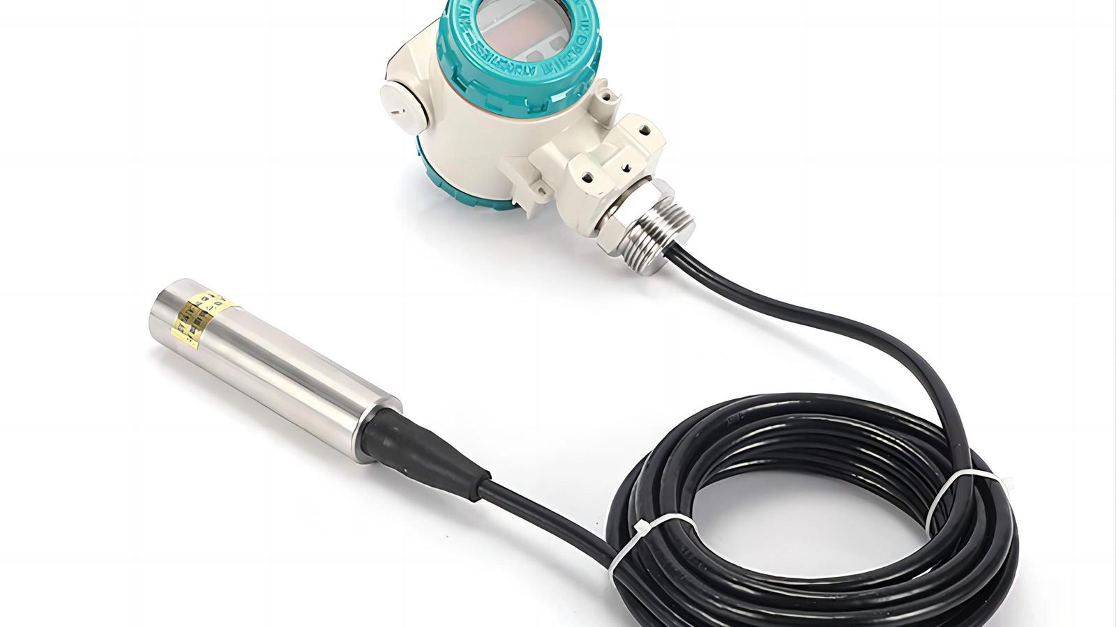
A submersible hydrostatic level transmitter is a pressure-based instrument lowered directly into a liquid that measures level by converting the hydrostatic pressure of the liquid column above its sensing diaphragm into a continuous level signal. A typical WELK submersible hydrostatic level transmitter delivers an accuracy of 0.5% FS, covers measurement ranges from 0–1 m up to 0–200 m, outputs 4–20 mA or RS-485 Modbus, and is sealed to IP68 so it can operate fully submerged for years. Because the sensor measures at the point of immersion rather than from above the liquid, it is the default technology for groundwater wells, reservoirs, wastewater sumps, and open tanks where a top-down instrument cannot be mounted or would be blocked by foam, vapor, or condensation. If you are sourcing from China for a process or environmental project, this guide walks through range, cable, vent tube, materials, and the applications where this sensor wins — and the few where it does not.
Selection is not one decision but a set of six that must match the physical site, the process fluid, and the control system receiving the signal. Working through them in order eliminates the majority of field failures before they happen.
The hydrostatic principle is simple: 1 m of water produces approximately 9.81 kPa (0.098 bar) of pressure at the diaphragm. For a 10 m well you need at least a 0–10 m range, and WELK submersible level transmitters are available from 0–1 m for shallow sumps up to 0–200 m for deep boreholes. The rule is to size the range slightly above the maximum expected level — for example a 0–12 m instrument on a 10 m well — so the sensor stays inside its linear span and never clips at the top of the signal.
Equally important is not to oversize. Accuracy is expressed as a percentage of full scale, so a 0.5% FS transmitter on a 0–200 m range carries a total error of ±1 m. Put that sensor in a 5 m sump and your "0.5% accuracy" becomes a 20% error in real terms. For deep groundwater monitoring, a purpose-built deep well level transmitter is ranged tightly to the borehole depth so the percentage error stays meaningful.
When a datasheet says 0.5% FS, it means the combined error from linearity, hysteresis, and repeatability stays within ±0.5% of the full-scale span across the operating temperature range. On a 10 m range that is ±50 mm — more than adequate for tank inventory, sump control, and groundwater trending. Two cautions apply. First, the error scales with span, so a tighter range always gives a tighter absolute reading. Second, temperature drift matters in outdoor installations: a sensor rated 0.5% FS at 25 °C may drift by several mm/°C near the zero point, which is why WELK sensors compensate the signal electronically over the full –10 to +70 °C range and why you should request the temperature error specification, not just the base accuracy, before ordering.
Match the output to what your PLC, SCADA, or DCS expects. The two-wire 4–20 mA loop is the universal default, powered by the loop itself and immune to signal loss over long cable runs. RS-485 Modbus is the right choice when several transmitters share one cable in a multi-drop bus, which is common in reservoir and well-field telemetry. For remote configuration and diagnostics — re-ranging the instrument without pulling it from the well — a HART-enabled unit is worth the premium. WELK's smart hydrostatic level transmitter with HART supports both 4–20 mA and digital HART communication so your maintenance team can interrogate the device from the surface. State the output on your RFQ; retrofitting a different protocol later means pulling the sensor.
The most misunderstood specification on a submersible level transmitter is the vent tube, so it deserves a full explanation. A hydrostatic sensor measures total pressure at the diaphragm: the liquid head (ρ × g × h) plus atmospheric pressure at the surface. To report liquid level you must subtract the atmosphere. There are two ways to do that, and they define the two product families.
Vented (gauge) reference. A small-diameter vent tube runs from the back of the sensing element up through the cable to the surface, where it is open to atmosphere through a desiccant filter. Because the reference side breathes the surrounding air, barometric changes and temperature swings cancel out automatically. This is why the industry default for outdoor wells and open tanks is a vented level transmitter — it needs no correction and stays accurate across a storm front, a passing high-pressure system, or a day-to-night temperature swing.
Absolute reference. The reference side is sealed under vacuum. The sensor is cheaper and has one less opening, but it now sees the sum of liquid head plus atmospheric pressure, so the reading drifts with the weather. It is usable when the instrument is installed in a sealed tank with a pressurized gas space, where a vent tube cannot be exposed to atmosphere, or when the DCS applies barometric compensation from a separate pressure sensor.
The vent tube filter — the small cylindrical breather on the cable — is a consumable part, not a fitting. It keeps humidity and dust out of the reference line, and a blocked or waterlogged filter is the number-one cause of drift in vented transmitters. Plan a replacement schedule (typically every 6–24 months depending on humidity) and keep the filter oriented downward so rain cannot enter the breather.
Cable length is a separate line item from measurement range, and under-specifying it is the most common sourcing mistake. Total cable length must cover the vertical depth of the sensor, the horizontal run to the readout or junction box, and a service loop at the top. A 50 m well with a control cabinet 30 m away needs roughly 85–90 m of cable, not "a 50 m range." Specify the finished length on your RFQ so WELK terminates the cable at the correct dimension.
The cable construction matters as much as the length. Standard submersible cable uses PE or PUR insulation that resists water ingress along the conductor. In boreholes, where the cable rubs against steel casing every time the pump or sensor moves, an armored-cable hydrostatic level transmitter with steel-braid reinforcement protects the vent tube and conductors from abrasion that would otherwise ground a unit within months. In wastewater with oils and fats, specify a polyurethane jacket, which resists the hydrocarbons that soften PE over time.
Two electrical points. For a 4–20 mA loop the voltage drop across the cable is normally trivial — roughly 1 V per kilometer of 0.5 mm² conductor — but check that your supply voltage clears the transmitter's minimum (typically 12–36 VDC) after the drop at the far end of a long run. And never bend the cable tighter than its minimum radius or kink the vent tube: a pinched reference line behaves exactly like a blocked filter and produces a slow, hard-to-diagnose drift.
The wetted materials — diaphragm, sensor body, and cable jacket — must be compatible with the process fluid. There is no universal material, and this is where the "works in water" assumption causes the most write-offs.
316L stainless steel is the default for clean water: groundwater, drinking water, and most industrial water. It is corrosion-resistant, handles the full pressure range including deep wells, and is the most economical option. For potable service, WELK's drinking-water hydrostatic level probe is manufactured in 316L with a food-grade silicone-free cable so it can be submerged in mains or reservoir water without contaminating the supply.
PVC bodies suit general wastewater and mildly aggressive media where the cost of stainless is unjustified. They are light, cheap, and adequate for municipal sewage and stormwater, provided the fluid contains no strong solvents.
PTFE (Teflon)-faced diaphragms are specified for aggressive chemicals — acids, caustic solutions, and chemical sumps — where 316L would pit or corrode. Pair a PTFE diaphragm with a matching cable jacket because the cable is as much a wetted part as the sensor body. For wastewater and lift-station duty, a wastewater hydrostatic level transmitter with a PTFE or 316L flush diaphragm resists the solids and grease that clog a standard probe.
Two related specifications worth knowing. A flush diaphragm sits level with the housing, giving viscous or solids-laden media nothing to collect in, which prevents the mudding that slows response on standard recessed diaphragms. And for narrow boreholes and standpipes, small-diameter transmitters (Ø 22 mm class) pass through 1-inch casing and drop-in monitoring wells where a standard body will not fit.
Get the environment right and this sensor is practically maintenance-free. Its natural applications are:
It fails in a specific, predictable set of situations:
For open tanks and below-ground structures, the decision is usually between these three technologies. Each measures a different physical property, and the table below captures the practical differences a buyer or process engineer needs.
| Criterion | Submersible Hydrostatic | Ultrasonic | Radar |
|---|---|---|---|
| Measurement principle | Liquid head pressure at depth | Sound transit time from above | Electromagnetic wave from above |
| Typical accuracy | 0.5% FS (≈ ±0.5% of span) | ±0.2–0.5% of reading | ±1–3 mm (FMCW) |
| Typical range | 0–1 m to 0–200 m | 0.3–15 m typical | 0.1–70 m typical |
| Installation point | Bottom / at depth | Top; above liquid | Top; above liquid |
| Effect of foam; vapor; condensation | None | Significant — false echoes or lost signal | Minor to none |
| Effect of temperature; weather | Low (vented reference) | Significant — sound speed varies | Minimal |
| Moving/coating surface interference | None | Coating on transducer attenuates | Buildup on antenna attenuates |
| Blockage by rags; grease; floating solids | Not affected | Not affected (reads top) | Not affected |
| Contact with process fluid | Yes; wetted | No | No |
| Suitability for narrow boreholes / deep wells | Excellent | Poor — beam spread and near-blank | Limited in narrow casing |
| Typical cost | Lowest | Low–medium | Highest |
| Typical accuracy quoted | 0.5% FS | ±0.2–0.5% | ±1–3 mm |
The decision rule is short. For deep, narrow, underground structures — wells, boreholes, sumps, standpipes — the submersible hydrostatic transmitter is usually the only practical option, because ultrasonic cannot reach into a narrow column and radar is oversized and blocked by narrow casing. For wide-open tanks with a clean surface and a mounting point overhead, radar or ultrasonic gives point-in-space accuracy without wetted parts. For wastewater, the submersible probe's immunity to foam and condensation is often the deciding advantage, which is why lift stations overwhelmingly use hydrostatic sensors.
What is the difference between a submersible hydrostatic level transmitter and a pressure transmitter?
Both use the same hydrostatic principle. The submersible level transmitter is packaged for immersion — sealed to IP68, fitted with a vented cable and breather, and rated for the environment inside a well or tank. A general-purpose pressure transmitter is built for pipe or tank wall mounting, not continuous submersion.
How do I choose between vented and absolute submersible level transmitters?
For open tanks, wells, reservoirs, and sumps, always choose vented. The vent tube cancels barometric changes automatically. Choose absolute only for sealed tanks with a pressurized gas space, or when a separate barometric correction is applied by the DCS.
What cable length do I need?
The cable must cover the vertical depth to the sensor, the horizontal run to the control panel, plus a service loop — typically 10–20% more than the measurement depth alone. Specify the finished length in your RFQ; the range and the cable length are two separate items.
Can a submersible level transmitter measure depth to 200 m?
Yes. Hydrostatic sensors scale with pressure, and WELK builds deep-well versions rated to 0–200 m. Accuracy remains 0.5% FS, so for a deep borehole you should range the instrument close to the actual depth rather than oversize it.
Will a submersible level transmitter work in sludge and wastewater?
Yes, if the wetted materials are specified correctly — a PTFE or flush diaphragm for solids-laden media, a PUR or armored cable for abrasion, and a body material compatible with the fluid's chemistry. Standard 316L is fine for clean wastewater; aggressive chemicals need PTFE.
Sourcing a submersible hydrostatic level transmitter for a well, reservoir, sump, or borehole does not have to be a guessing game. Send WELK's sales team your basic specification — media and its chemistry, maximum and minimum level, measurement depth, temperature, required output (4–20 mA, RS-485 Modbus, or HART), and the cable run distance — and they will recommend the exact model, range, material, and cable configuration for your application, free of charge. To make sure you have every parameter ready, use our hydrostatic level transmitter RFQ checklist before you write in. All WELK transmitters are manufactured and fully tested in our own factory under quality control procedures, so you get a sensor matched to your process and priced for direct-from-manufacturer procurement. Send your spec today and get a documented selection recommendation within one working day.
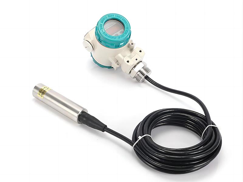
Submersible hydrostatic level transmitter for wells, reservoirs, tanks and water projects with cable length and output configured by depth.
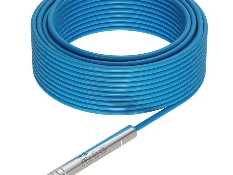
Submersible deep-well level transmitter with long cable, IP68 probe and output selected for groundwater or reservoir monitoring.
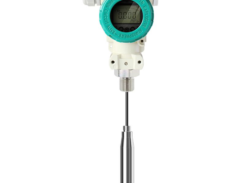
Smart hydrostatic level package with local display, analog output and digital communication options for tank and well monitoring.
Send drawings, dimensions, material, environment or operating conditions, and we will help confirm the right specification.
Uploaded reference files are included with the inquiry. For larger CAD packages, reply to the confirmation email or send them here:
Our team typically replies within 24 hours.