Technical
Magnetic Level Gauge Working Principle: Float & Flags
How does a magnetic level gauge work? Float-and-flag principle, materials, transmitter options, and when it beats a sight glass. Contact WELK for a quote.
How does a magnetic level gauge work? Float-and-flag principle, materials, transmitter options, and when it beats a sight glass. Contact WELK for a quote.
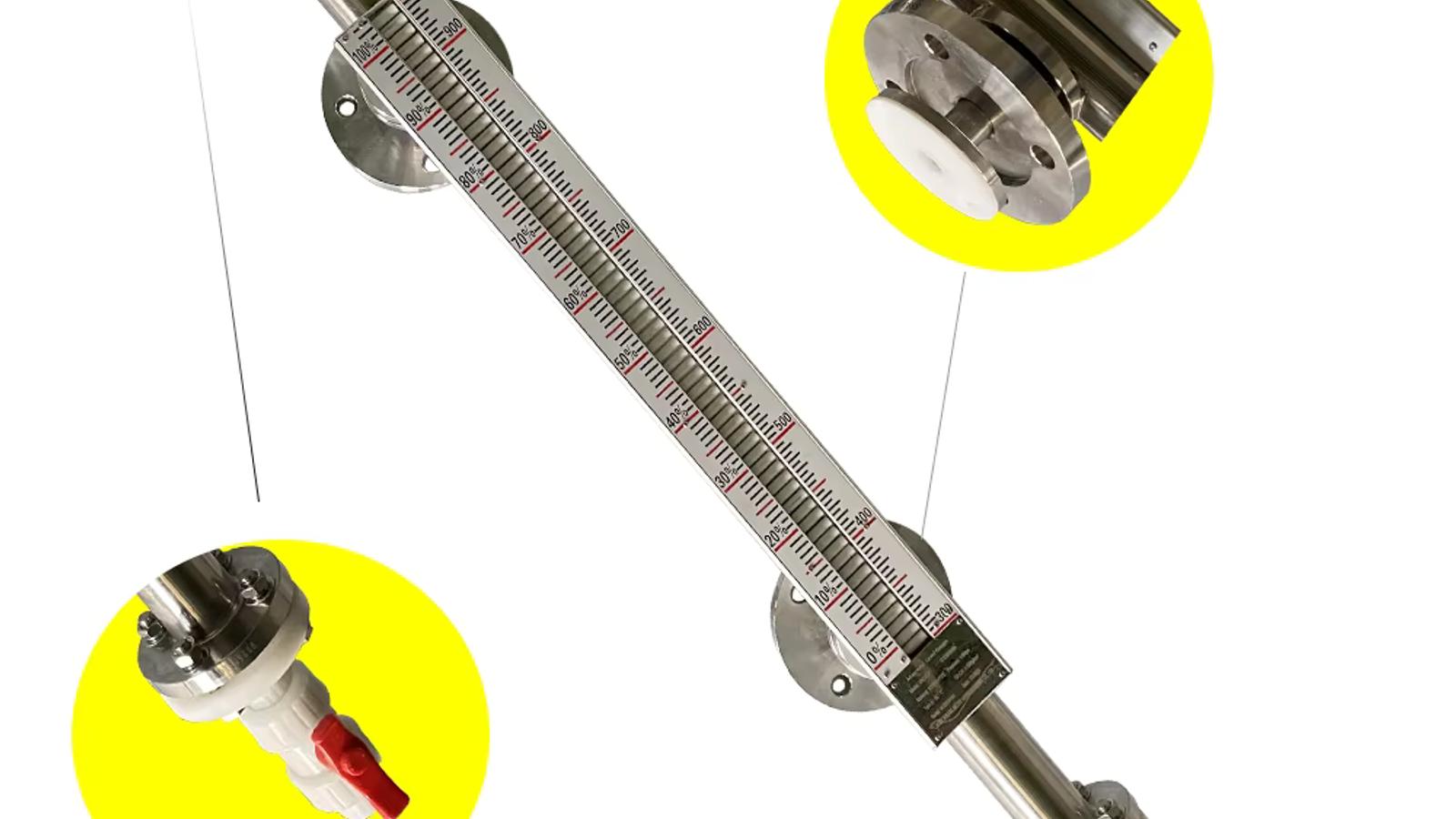
A magnetic level gauge (also called a magnetic flap level gauge or magnetic level indicator) is a visual level instrument that uses a sealed float with internal permanent magnets to track liquid level inside a chamber connected to the process tank. The float rises and falls with the liquid surface according to Archimedes' buoyancy principle, and its magnetic field flips a column of bi-colour flags (red and white) 180° on the outside of the chamber, producing a clear at-a-glance display with a typical visual accuracy of ±10–20 mm. An optional magnetostrictive or 4–20 mA transmitter can be fitted to the same chamber to provide a continuous electronic level signal to a PLC, DCS, or SCADA system.
A complete magnetic level gauge is a four-part assembly: the measuring chamber, the float, the external flag indicator, and, when remote signalling is required, a transmitter. Here is how the measurement happens, one step at a time.
The heart of the instrument is the float — a hollow, hermetically sealed cylinder made of 316L stainless steel or a corrosion-resistant alloy, with permanent magnets mounted inside. The float's average density is engineered so it floats in the process liquid with roughly one-third to one-half of its volume submerged. As the tank level rises, the liquid lifts the float up; as the level falls, the float drops with it. Because the float moves freely inside the chamber, it always sits exactly at the liquid surface (or at the interface between two liquids of different density, when configured for interface measurement).
The float travels inside the measuring chamber, a vertical length of pipe connected to the tank through two nozzles — one at the top and one at the bottom (for side-mounted versions). The chamber is essentially a small external standpipe that communicates with the tank through the connecting pipes, so the liquid level inside the chamber always matches the level inside the tank, by the principle of communicating vessels. The two isolation valves on the connections let you service or remove the gauge without draining the tank.
The chamber wall is made of a non-magnetic material — austenitic stainless steel such as 316L is the standard — so the float's magnetic field passes through it almost unimpeded. This is the key trick of the design: the process side and the indication side are completely separated by the metal wall, yet still coupled magnetically. The float's magnets act as the "transmitter" side of a magnetic coupling, and the flags on the outside are the "receiver."
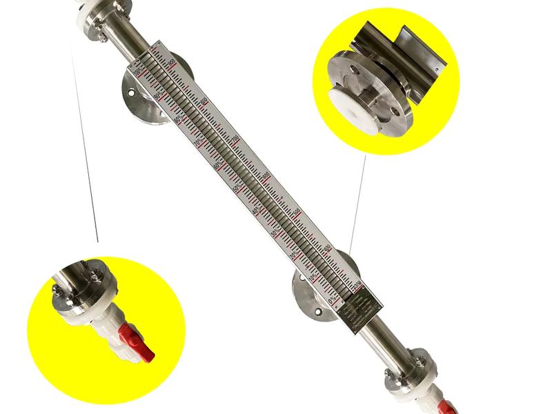
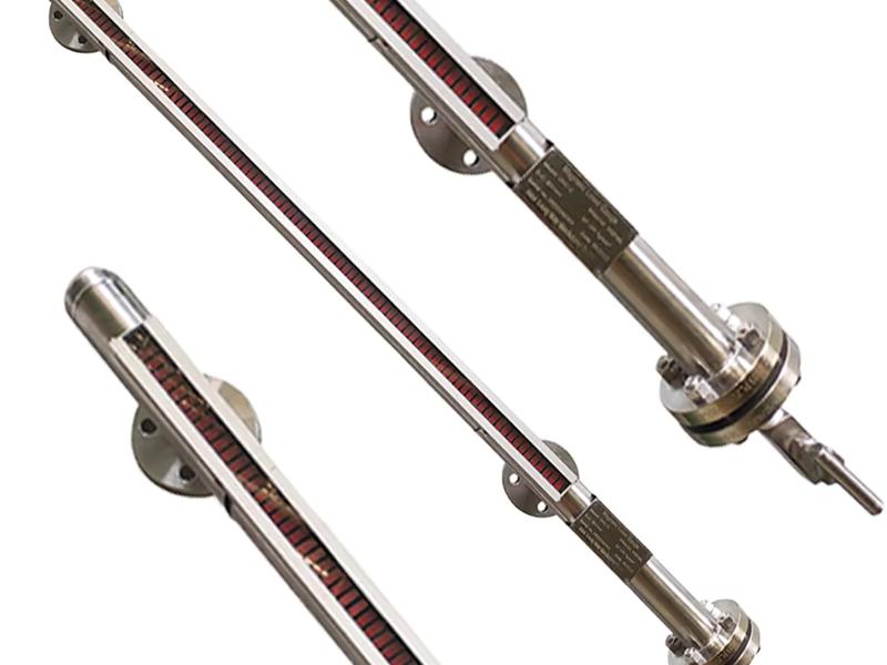
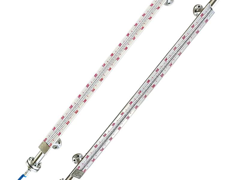
Outside the chamber, a column of small pivoting blades called flags (or tablets, or wafers) is mounted. Each flag is itself a tiny magnet assembly, painted red on one side and white on the other. As the float passes a flag, its strong magnetic field overcomes the flag's holding force and flips the blade 180°. Flags below the float turn red, flags above the float stay white, and the boundary between red and white marks the exact liquid level. The display needs no electrical power and can be read from several metres away.
Because the float is the only moving part in the process, the same float position can be converted to an electronic signal. A magnetostrictive transmitter drops a waveguide tube inside the chamber, and a 4–20 mA/HART transmitter can be mounted on top of the chamber. Both detect the float's magnet position and convert it to a continuous output. In this way one magnetic level gauge provides both a local visual readout and a remote signal from a single device.
The magnetic level indicator working principle rests on two physics fundamentals: buoyancy and magnetic coupling. Understanding both helps you specify the right instrument and avoid field failures.
The float obeys Archimedes' principle: an object submerged in a fluid experiences an upward buoyant force equal to the weight of the fluid it displaces. When the float is partially submerged, the buoyant force balances its weight, and the float settles at a stable position that depends only on the liquid density and the float's geometry. As the level changes, the float moves to re-establish equilibrium — so the float's position is a direct, repeatable measure of liquid level. This is why density matters: the process liquid must be dense enough (typically above 0.45–0.50 g/cm³) to lift the float. If you are measuring a low-density hydrocarbon or liquefied gas, the float must be sized and weighted specifically for that density.
The second principle is magnetic coupling through a non-magnetic barrier. Magnetic fields pass through austenitic stainless steel, so the float's magnets can flip the external flags without any opening, seal, or mechanical linkage in the chamber wall. This is what gives the magnetic level gauge its defining safety advantage: there is no glass window, no packing gland, and no moving shaft passing through the vessel wall.
A sight glass must be a physical window in the vessel wall — a structural weak point that sees full process pressure and is vulnerable to thermal shock, mechanical impact, and chemical attack. A mechanical float-and-lever gauge needs a rotating or sliding shaft through the wall, which means a dynamic seal that can wear and leak. The magnetic level gauge has neither. The process fluid is fully contained inside a pressure-rated chamber, and every indication element sits on the outside. For toxic, corrosive, flammable, or high-pressure media, that separation is the entire point.
The flag column is the most visible part of the magnetic level gauge, and it deserves a closer look. Each flag is a small rectangular blade, typically 50–120 mm long, pivoted at its centre and fitted with small permanent magnets on its lower edge. The magnets give each flag two stable positions — red forward or white forward — so the display "snaps" cleanly from one colour to the other rather than sitting halfway.
The red/white colour scheme is deliberate. In the conventional arrangement, the flags below the liquid level show red (indicating the liquid-filled portion) and the flags above show white, giving a clear level line at the red/white boundary. Some manufacturers use red/green or red/silver schemes for improved contrast in specific applications. Because the flag assembly is completely separate from the pressure-containing chamber, it can be replaced or maintained — even cleaned or upgraded to an illuminated or heated version — without ever breaking the process seal. In dark or outdoor locations, a light strip or an LED version can be fitted behind the flag column so the level remains visible at night.
Material selection is where a magnetic level gauge is either made or broken, because the float, chamber, and sealing system must all survive the process while remaining magnetic and leak-tight.
For acid and alkali service, the wetted parts are the decisive factor. If the media would attack standard 316L, specify an anti-corrosion lined magnetic level gauge with PTFE or PFA lining and a float that is likewise protected. Getting this wrong is the most common cause of premature magnetic level gauge failure.
The basic principle stays the same across the product range, but the mechanical configuration changes with the application.
The most common arrangement. The chamber is bolted to the side of the tank through two flanged nozzles, and the flag column runs alongside the chamber. This is the standard choice for atmospheric and medium-pressure storage tanks, and it is the easiest to retrofit to an existing tank with side nozzles. See the side-mounted magnetic level gauge for full specifications.
When a tank has no side nozzles — for example, underground tanks, pressurised vessels, or tanks that are already in service — a top-mounted magnetic level gauge is used. The float rides on a guided rod inserted from the top nozzle, and the flag column is mounted above. This variant is common for skids, mobile tanks, and retrofit projects.
For media that solidify, crystallise, or become too viscous to move the float at ambient temperature — such as sulphur, bitumen, heavy fuel oil, or paraffin — a steam jacketed magnetic level gauge circulates steam or hot water around the chamber to keep the media fluid and maintain accurate level measurement. For outdoor installations in cold climates, an insulated, frost-proof magnetic level gauge keeps the media from freezing and prevents condensation inside the indicator.
Standard gauges are typically rated to about 2.5 MPa. For high-pressure service, the chamber walls are thickened, the flanges are upgraded (ANSI Class 150–2500 or equivalent), and the float is pressure-verified. A high-pressure magnetic level gauge is used on boiler drums, ammonia storage, and other pressurised vessels, with ratings that extend well above 10 MPa depending on the design. Temperature range is typically −40 °C to +350 °C for standard versions, extending to roughly −196 °C for cryogenic service and up to +450 °C with steam jacketing.
A purely visual gauge is fine when someone is physically present, but modern plants want the level in the control room. The good news is that the visual and electronic measurement can share one chamber and one float.
Two transmitter technologies are common:
Either option bolts onto the existing chamber, so you get a local flag readout and a remote signal from one instrument. The magnetic float level transmitter 4–20 mA is the usual retrofit solution. If your control system communicates digitally, you may also want to read our comparison of 4-20 mA vs HART vs Modbus RS-485 to match the output to your installed infrastructure.
Each technology answers the same question — "how much liquid is in this vessel?" — with a different trade-off. The table below summarises the practical differences for a procurement engineer.
| Characteristic | Magnetic Level Gauge | Sight Glass | Magnetostrictive Transmitter | Guided Wave Radar |
|---|---|---|---|---|
| Principle | Buoyant float + magnetic flags | Direct visual through glass | Magnetic float on a waveguide | Radar pulse along a probe |
| Typical accuracy | ±10–20 mm visual; ±1–5 mm with transmitter | ±5–20 mm (reading quality dependent) | ±1–2 mm | ±2–5 mm |
| Local visual readout | Yes (flags; no power) | Yes (direct view) | No (electronic only) | No (electronic only) |
| Remote output | Optional 4–20 mA/HART | No | Yes; 4–20 mA/HART | Yes; 4–20 mA/HART; fieldbus |
| Wetted parts in process | Chamber + sealed float only | Glass; gaskets; pipe | Chamber + float | Probe in direct contact |
| Leak risk | Very low (no dynamic seal; no glass) | High (glass window at full pressure) | Very low | Low (single top entry) |
| Toxic/corrosive/high-pressure media | Excellent | Poor | Excellent | Good |
| Power required | None for indication | None | Yes (electronics) | Yes (electronics) |
| Relative cost | Moderate | Lowest | Moderate–high | High |
The short version: a sight glass is cheapest but weakest, guided wave radar is the most flexible but costs more and needs power, magnetostrictive is the accuracy leader, and the magnetic level gauge is the balanced workhorse that combines a free local display with an optional electronic output.
Sight glasses still appear on many plants, but they lose on four specific fronts:
That is why magnetic level gauges are the standard choice for boiler drums, chemical storage, and high-pressure vessels — see our guides on boiler drum level measurement and level measurement technologies compared for more context.
The magnetic level gauge is not a universal answer. It struggles with media below its minimum float density, fluids that coat the float and prevent free movement, liquids carrying ferromagnetic particles that cling to the magnets, and very high-temperature services beyond the magnet's rating. For those, a point vs continuous level measurement analysis will point you to radar, capacitance, or another technology. But for the majority of liquid storage and process applications, the magnetic level gauge delivers safety, simplicity, and reliability at a price that is hard to beat.
A magnetic level gauge is mechanically simple, but it rewards correct installation and routine care.
Installation:
Maintenance:
With this routine, a magnetic level gauge typically runs for years with nothing more than occasional flag cleaning and a transmitter check.
How accurate is a magnetic level gauge? The visual flag display is accurate to approximately ±10–20 mm, which is fine for storage and process indication. Adding a magnetostrictive transmitter improves the electronic reading to roughly ±1–2 mm, and a magnetic float 4–20 mA transmitter gives about ±5–10 mm.
What is the difference between a magnetic level gauge and a sight glass? A sight glass is a transparent window in the vessel wall that shows the liquid directly, but it is a pressure-boundary weak point that can crack, fog, and foul. A magnetic level gauge seals the liquid in a chamber and displays the level through external magnetic flags, so it is safer, more visible, and can output an electronic signal.
Does a magnetic level gauge need electricity? No. The flag indication is entirely mechanical and magnetic, so it works with no power supply — an advantage during power loss and in hazardous areas. Electricity is only needed if you add a transmitter or an illuminated indicator.
Which liquids can a magnetic level gauge measure? Any liquid dense enough to float the float, typically above 0.45–0.50 g/cm³, including water, oils, chemicals, acids, and cryogenic fluids, plus interfaces between two immiscible liquids. It is not suitable for media that coat the float, or liquids carrying ferromagnetic particles.
Can I add a 4–20 mA transmitter to an existing magnetic level gauge? Yes, in most cases. A magnetostrictive or magnetic float transmitter can be retrofitted to an existing chamber without breaking the process seal, giving you a continuous signal to the control room alongside the existing visual display.
Specifying the right magnetic level gauge comes down to your process conditions: working pressure, operating temperature, media and its density, tank connection size, and whether you need a remote signal. If you are replacing a sight glass, upgrading from manual gauging, or designing a new vessel, contact WELK with your tank pressure, temperature, media, and connection details — our engineers will recommend the correct material, float, and transmitter configuration for your application.
Magnetic level gauge for local indication on pressure vessels up to 16 MPa and 350 C.
Bypass chamber magnetic level gauge for side-side or side-bottom vessel connections.
Engineered magnetic level gauge for pressure vessels, separators and demanding process conditions.
Send drawings, dimensions, material, environment or operating conditions, and we will help confirm the right specification.
Uploaded reference files are included with the inquiry. For larger CAD packages, reply to the confirmation email or send them here:
Our team typically replies within 24 hours.