Guided wave radar (GWR) and non-contact radar are the two dominant radar level measurement technologies in the process industry, and choosing between them comes down to tank geometry and process conditions rather than raw capability. A guided wave radar transmitter measures level by sending low-energy microwave pulses down a cable or rod probe and timing the reflection from the media surface using time-domain reflectometry (TDR), delivering accuracy to ±2 mm and working on media with a dielectric constant as low as 1.4. A non-contact radar level meter uses frequency-modulated continuous wave (FMCW) technology at 80 GHz to measure level from above the media with no physical contact, achieving the same ±2 mm accuracy through a narrow 3–8 degree beam angle. Both are produced under ISO 9001 factory quality systems with ATEX/IECEx options available, but they are far from interchangeable: each fails in different process conditions, and selecting the wrong one for your tank costs you false readings, recurring maintenance, and unplanned downtime. This selection guide compares how the two technologies work, where each breaks down, and how to match the right instrument to your vessel.
The table below summarizes the operational differences that drive most selection decisions. Read the sections that follow for the reasoning behind each row.
| Feature | Guided Wave Radar (TDR) | Non-Contact Radar (FMCW 80 GHz) |
|---|
| Accuracy | ±2 mm across the measuring range | ±2 mm across the measuring range |
| Blind zone | None; measures down to the probe tip | Typically 50–100 mm below the flange; grows with some designs |
| Minimum dielectric constant | Works to as low as 1.4 | Reliable above ~1.5–1.8; weak reflections below that |
| Foam tolerance | Good with light foam; heavy foam still attenuates the pulse | Heavy foam absorbs and scatters the beam; causing erratic readings |
| Condensation tolerance | Excellent; probe handles vapor and condensation | Moderate; condensation on the antenna weakens the signal unless purged or coated |
| Sticky / coating media | Build-up on the probe changes the reflection and causes drift | No probe in the media; coating only affects the antenna |
| Agitators / obstacles in tank | Probe can be struck; bent; or broken; must be kept clear | Beam tolerates internals better if the 3–8 degree angle keeps them out of the path |
| Installation | Nozzle must clear the probe; probe must hang vertical and free of internals | Mounts on a standard nozzle; needs beam-angle clearance |
| Maintenance | Probe cleaning required with sticky media; inspect probe for coating | Periodic antenna inspection; no probe to foul |
| Cost | Lower unit price; typical entry point into radar | Higher unit price; premium for nozzle and certification options |
| Best application | Small tanks; tight spaces; low-dielectric media; condensation-heavy and high-temperature service | Large tanks; tall silos; aggressive media; and surfaces with changing profiles |
How Guided Wave Radar Works: Time-Domain Reflectometry
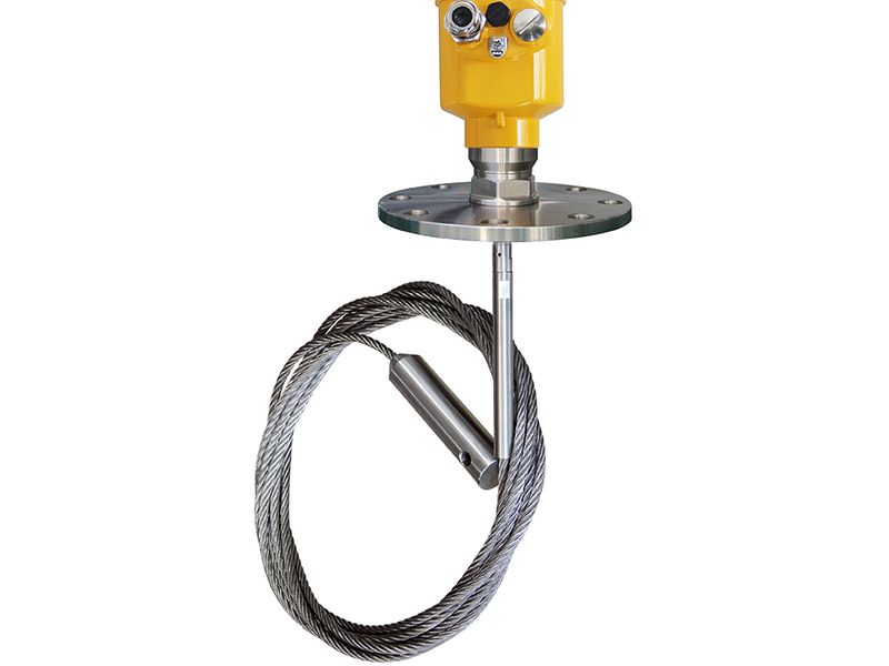
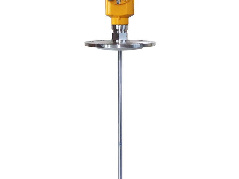
A guided wave radar transmitter generates low-energy microwave pulses that travel down a probe — a steel cable, rigid rod, or coaxial assembly — and reflect off the surface where the media meets the vapor phase. Because the pulse travels along a defined conductor rather than through open air, the signal path is predictable and the return echo is strong, even when the media above the probe offers very little reflection in free space. The instrument measures the time between pulse launch and echo return, converts that time into distance using the propagation speed in the probe, and subtracts it from the installed reference height to report level.
Three probe geometries cover nearly every guided wave application. A cable guided wave radar suits tall vessels where a rigid probe would be impractical, with measuring ranges that extend well beyond what a rod can offer. A rod guided wave radar provides the stiffness and short-range accuracy needed for small tanks and tight nozzles. Coaxial probes add a shield that virtually eliminates interference from vessel walls and nearby internals, at the cost of a more expensive assembly. The choice of probe directly affects range, chemical compatibility, and how much clearance your nozzle must provide.
Because the pulse is guided, the energy reaches the media surface reliably at low dielectric constants. TDR instruments operate on media with a dielectric constant as low as 1.4 — a range that includes liquefied gases and several hydrocarbons that free-space radar struggles to detect. The guided design also creates no meaningful blind zone: the reference point is at the probe connection, and the instrument can report level all the way down to the probe tip, which makes it ideal for small tanks where the liquid level may approach the tank bottom. High-temperature and high-pressure variants extend guided wave radar into boiler and process-vessel service where the probe simply needs to survive the conditions in contact with the media.
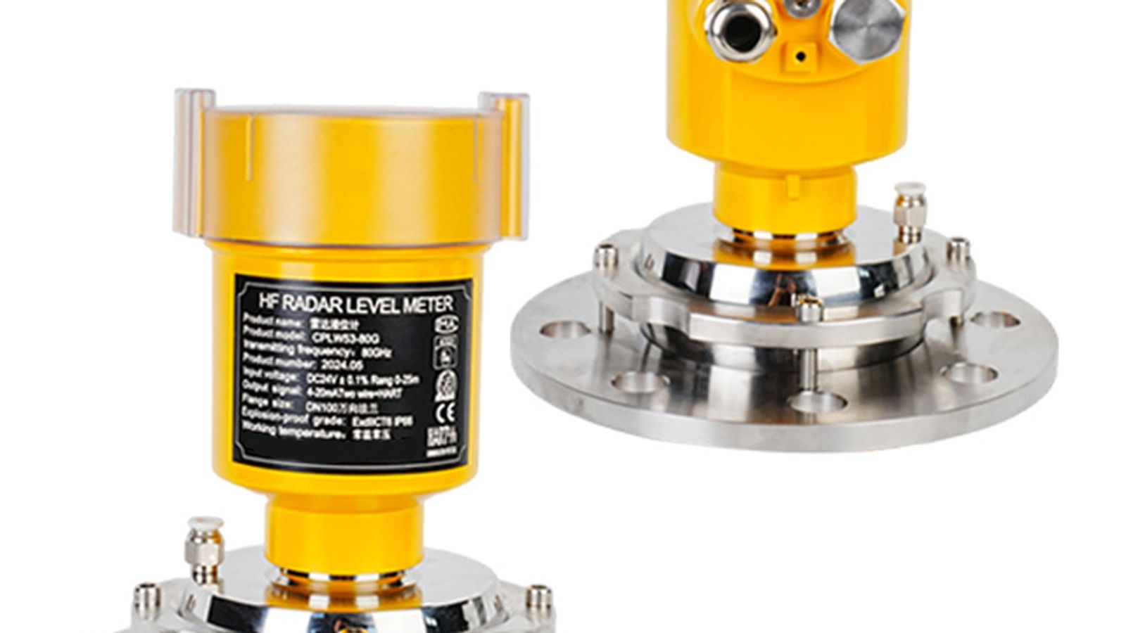
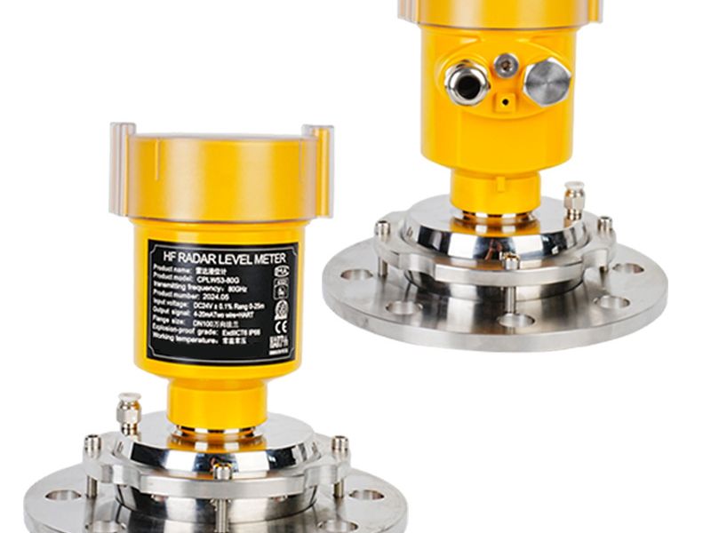
A non-contact radar level meter takes a fundamentally different measurement approach. Instead of firing a short pulse, the FMCW transmitter sweeps continuously across a frequency band — 80 GHz in modern instruments — and compares the frequency of the transmitted signal with the frequency of the echo reflected from the media surface. The frequency difference between the two is directly proportional to the distance traveled, so the instrument derives level from a precise frequency measurement rather than a timing measurement. This continuous sweep makes FMCW highly linear and stable, and it is why most modern non-contact radar instruments specify ±2 mm accuracy despite no physical contact with the media.
The 80 GHz band is what makes modern non-contact radar attractive. At these frequencies, the microwave beam is narrow — roughly 3–8 degrees — so the illuminated spot on the media surface stays small even in tall tanks. A narrow beam means less interference from tank walls, ladders, and nozzles, and it allows the instrument to be mounted in locations where a wide-beam sensor would pick up stray echoes from internal structures. The higher frequency also enables smaller antennas and lighter instruments, which simplifies installation on nozzles and stilling pipes. In large vessels, silos, and hoppers, the 80 GHz non-contact radar level meter can measure over ranges that guided wave probes would struggle to support economically, because the free-beam approach is not limited by probe length or cable weight.
Non-contact radar works best when the media surface is clean, flat, or only gently agitated, and when the dielectric constant is high enough to return a usable echo. Because there is no probe, there is nothing in the vessel to corrode, coat, or be struck by an agitator — which is precisely why many plants choose free-beam radar for aggressive or moving processes.
Accuracy Compared: Which One Really Measures to ±2 mm?
Both technologies claim ±2 mm accuracy, and under the right conditions both deliver it. The difference is where that accuracy holds up.
Guided wave radar maintains its ±2 mm spec in conditions that would defeat a free-beam unit. Because the pulse is confined to the probe, the measurement is insensitive to vapor, foam thickness, condensation, and vessel geometry. Accuracy holds even in very low dielectric media, where the strong guided echo is unaffected by the weak free-space reflectivity. The trade-off is that accuracy depends on the probe being installed correctly: a probe touching the tank wall or an internal, or one that is not vertical, introduces error. There is also no blind zone, which matters when the full range of the tank, right down to the bottom, is usable volume.
Non-contact radar holds ±2 mm when the surface returns a clean echo. In a large tank with a stable surface, an 80 GHz FMCW unit is exceptionally repeatable, and its accuracy is unaffected by process conditions because nothing touches the media. However, the ±2 mm figure is conditional on signal quality. If the beam angle lets an internal structure enter the measurement path, if heavy foam dampens the echo, or if condensation forms on the antenna, the reported level can drift well beyond spec before the signal is lost entirely. Low-dielectric media compound the problem: below roughly 1.5–1.8, the reflected energy may be too weak for reliable measurement, and the instrument either reports false echoes or requires special antenna designs.
If you are weighing radar against a completely different technology, our radar vs ultrasonic level meter guide covers where ultrasonic — which is often cheaper but far more sensitive to foam, vapor, and temperature — still makes sense.
Where Each Technology Fails
No level instrument is universal. The fastest way to pick the wrong transmitter is to assume that more expensive means more capable.
- Heavy foam. Foam absorbs and scatters microwaves. A dense foam layer can attenuate the beam to the point where the echo is lost, and the instrument may report the foam surface rather than the liquid beneath it. Non-contact radar has no way to see through it.
- Heavy condensation and steam. Condensation on the antenna face weakens the transmitted signal. In vessels with aggressive steam or condensation cycles, the antenna needs air purge or a hydrophobic coating, and even then readings can degrade.
- Very low dielectric media. Below a dielectric constant of roughly 1.5–1.8, the free-space reflection is weak. Non-contact radar can struggle with liquefied gases and some hydrocarbons, where a guided wave unit is unaffected.
- Crowded vessels. Although a narrow 3–8 degree beam helps, internal baffles, heat exchangers, and agitator blades that enter the beam path produce spurious echoes that must be filtered by echo tracking software. In the worst cases the instrument locks onto a false target.
- Tall nozzles. A long nozzle acts like a waveguide and distorts the beam. Non-contact radar requires a minimum nozzle height relative to its diameter, which must be checked before installation.
Where Guided Wave Radar Fails
- Sticky and coating media. The probe sits inside the media, so viscous or build-up-prone products can coat it. A coating layer changes the dielectric environment around the probe, slows the pulse, and shifts the apparent level. In extreme cases, build-up can bridge the probe to the vessel wall and destroy the reading. This is the single most common reason plants replace guided wave units.
- Agitators and moving internals. A rigid probe can be struck and bent by an agitator blade; a cable probe can be entangled. Protecting the probe with a stilling well or pipe adds cost and complexity, and in many installations it is simply not feasible.
- Applications where the probe cannot touch the media. Sanitary processes, vessels with heavy solids deposition, and some hygienic food applications cannot tolerate an in-contact probe. If the product cannot touch the instrument element, guided wave is disqualified by definition.
- Very tall vessels. A cable probe for a 30-meter silo is long, heavy, and vulnerable. Beyond a certain range, free-beam radar is the practical — and cheaper — answer.
This failure profile maps directly onto applications. In a cement silo, powder build-up and a tall vessel make non-contact radar the standard choice. In a small solvent storage tank with low dielectric media and possible condensation, guided wave is usually more reliable. If you are working with powders and bulk solids, our Silo & Powder Level application page explains how these same trade-offs play out at scale.
The physical difference between the two technologies drives very different installation requirements, and these often matter as much as accuracy when you are retrofitting an existing tank.
Guided wave radar needs the probe to hang free. The nozzle must be large enough to admit the probe (or the probe must be inserted through an open manway), and the probe must stay at least 100–300 mm away from the tank wall and from any internal structure to avoid false echoes. In a tank with agitators, the probe must be positioned where the blades cannot reach it — often in a stilling well. The probe must also be vertical: a rigid rod that leans against the wall reads incorrectly, and a cable probe that swings under flow conditions can wander outside its calibration path. Where tank height exceeds the practical probe length, or where the process cannot be interrupted for a long probe installation, non-contact is often the simpler retrofit.
Non-contact radar has simpler mechanical demands but its own geometric rules. The instrument mounts on a standard process nozzle, and the governing constraint is beam angle: at 80 GHz the 3–8 degree beam means that at a 10-meter distance the illuminated spot is roughly 0.5–1.4 meters across, so the nozzle and the space around it must be free of obstructions that would enter that cone. The instrument should also be mounted perpendicular to the expected media surface, or the echo can be deflected away from the antenna. On the plus side, nothing inside the tank needs modification — there is no probe, no stilling well, and no contact with the media.
Maintenance follows the same pattern. Guided wave instruments occasionally need probe cleaning and re-verification, particularly in coating service. Non-contact units need periodic antenna inspection, and in condensation-prone environments, scheduled checks for moisture on the antenna face. For applications where the probe would be exposed to extreme heat, a high-temperature radar level meter designed for the service is worth reviewing before you commit to a mounting strategy.
Cost Comparison: Purchase Price vs Lifetime Cost
Guided wave radar is generally the lower-cost entry point into radar level measurement. The electronics are simpler, the probe replaces the antenna assembly, and the mounting hardware is minimal. For a small tank with a standard nozzle, a guided wave transmitter is often the cheapest way to get radar-grade accuracy, and its lack of a blind zone means you may not need a second sensor for the lower portion of the tank.
Non-contact radar, especially at 80 GHz, commands a higher unit price. The FMCW signal chain, the compact antenna, and the beam-shaping optics are more sophisticated, and certification options add further cost. That premium buys physical separation from the process: no probe to clean, no probe to bend, and no media contact at all.
The lifetime cost comparison flips the purchase price. A guided wave unit in sticky service will cost you labor and downtime for regular probe cleaning, and if build-up is severe, the instrument may fail between cleanings. A non-contact unit on the same tank — if the media produces a usable echo — needs only periodic antenna inspection. Conversely, a non-contact unit on a low-dielectric, foam-prone solvent tank will cost you repeated service visits and false-level alarms while a guided wave unit runs quietly for years. The cheapest instrument is the one that keeps measuring, and the right answer depends on your media, not your budget.
How to Choose: A Practical Decision Tree
Work through these questions in order, and you will land on the right technology in most cases.
- Can anything touch the media? If the process is sanitary, or the product cannot tolerate an in-contact probe, choose non-contact radar.
- Is the media sticky, coating, or prone to heavy build-up on any inserted element? Choose non-contact radar. A probe will drift and eventually fail.
- Is there an agitator, mixer, or dense cluster of internals in the tank? Non-contact radar tolerates this far better, provided the beam path stays clear. If a probe is mandatory, plan a stilling well.
- Does the media foam heavily, condense aggressively, or have a dielectric constant below roughly 1.5? Choose guided wave radar. These are precisely the conditions that defeat free-beam measurement.
- Is the vessel short with a usable range down to the bottom, or does it require tight accuracy in a small tank? Guided wave radar's lack of a blind zone and its strong guided echo make it the better fit.
- Is the vessel tall — a silo, hopper, or large storage tank — or is the surface highly agitated or dusty? Choose non-contact radar. Probe length, weight, and swing make guided wave impractical beyond a point.
- Is the service high temperature or high pressure? Both technologies have variants rated for severe service; review the probe material and the instrument's temperature/pressure limits against your design conditions before deciding.
When the media profile is ambiguous — moderate foam, borderline dielectric constant, occasional coating — a field trial on one nozzle is the fastest way to settle it. Many suppliers, including WELK, can size both options and let you validate against the actual process before you standardize.
FAQ
- Can a guided wave radar measure through foam?
Light foam that does not absorb the pulse is generally not a problem, because the pulse is confined to the probe and reaches the surface with strong energy. Heavy, dense foam attenuates the signal and can cause drift, so if your process produces thick foam, non-contact radar will not fix it either — it is worse in foam. Manage the foam or accept that no radar measures the true surface reliably.
- What dielectric constant is too low for non-contact radar?
A reliable lower boundary for standard non-contact instruments is roughly 1.5–1.8. Below that, the free-space reflection is too weak for consistent measurement. Guided wave radar works down to a dielectric constant of about 1.4, because the probe guides the pulse to the surface and back, so low-dielectric service is a guided wave strength.
- Which is more accurate: guided wave or non-contact radar?
Both are specified at ±2 mm under their respective ideal conditions. The deciding factor is process, not the number: guided wave holds accuracy through foam, condensation, vapor, and low-dielectric media, while non-contact holds accuracy when the surface returns a clean, unobstructed echo. Choose the technology whose ideal conditions match your tank.
- Can I replace a non-contact radar with a guided wave unit on the same nozzle?
Mechanically, it depends on nozzle diameter and height. The nozzle must admit the probe, and the probe must hang clear of tank internals — something a free-beam antenna never had to worry about. A guided wave retrofit usually requires verifying nozzle size, tank clearance, and agitator position before committing.
- How much clearance does each technology need during installation?
Guided wave requires the probe to stay roughly 100–300 mm from walls and internals and to remain vertical. Non-contact radar requires the beam cone — from a 3–8 degree angle at 80 GHz — to stay free of obstructions, and the antenna should point perpendicular to the surface. In both cases the nozzle must meet the instrument's minimum height/diameter requirements.
Get a Quote for the Right Level Transmitter
You now have the technical basis to shortlist the right technology — the next step is confirming it against your actual process conditions. WELK is a Chinese manufacturer of radar, ultrasonic, and guided wave level instruments, with engineering support for sizing, nozzle checks, and process-condition reviews. Send us your tank dimensions, media properties, dielectric constant, temperature, and pressure, and our engineers will recommend a guided wave or non-contact solution — including guided wave radar, 80 GHz non-contact radar, and compact transmitter options — with a quotation and typical delivery lead times. You can also take a factory tour to see our ISO 9001 production line before you decide. Request a quote through the contact form and get a sizing recommendation matched to your tank.