Open channel flow measurement is the determination of volumetric flow rate in a channel, culvert, or partially filled pipe where liquid moves under gravity with a free surface open to the atmosphere. Because the channel geometry is fixed and known, flow can be inferred from a single level measurement: an ultrasonic level transmitter measures the height of the water above a reference point — the head — and the transmitter or a flow computer converts that head into a flow rate using the discharge equation of the installed primary element, such as a V-notch weir or Parshall flume, or, for rectangular and natural channels, the Manning equation. This level-to-flow approach is specified across water and wastewater utilities because it is non-contact, low-maintenance, and typically accurate to ±1–2% of rate when the primary element is properly installed and the transducer correctly mounted. For plants that must measure effluent, irrigation deliveries, and stormwater continuously and defensibly, head-based ultrasonic measurement remains the most cost-effective standard.
Why Open Channel Flow Is Measured by Level
Open channels are everywhere in the water industry: influent and effluent channels at treatment plants, irrigation canals and turnouts, stormwater outfalls, and industrial discharge lines that empty into municipal sewers or receiving waters. The defining feature of open channel flow is the free surface. Unlike a closed pipe running full, where flow can be computed from a velocity measurement and the pipe's cross-sectional area, an open channel has a liquid level that rises and falls as flow changes — and that level is a direct, repeatable function of discharge, provided the flow is controlled by a known cross-section.
That is the key insight behind level-based flow measurement. If you install a hydraulic control structure of known shape — a weir that forces water to spill over its crest, or a flume that constricts the flow through a throat — then for that structure there is a unique relationship between the upstream water level (head) and the flow passing through. Measure the head accurately, and the flow follows from a simple calculation, with no moving parts, nothing inserted into the flow, and nothing to clog or foul. This is why the method remains the workhorse for water and wastewater level measurement duties from plant influent to final effluent.
The relationship is described by a discharge equation of the general form Q = C·h^n, where Q is the flow rate, C is a coefficient that depends on the geometry of the structure and the units used, h is the head measured above a reference elevation, and n is an exponent determined by the shape of the structure. This is also why primary elements are built to precise dimensions: the accuracy of the whole measurement inherits from the known geometry and the head reading.
Primary Elements and Their Discharge Equations
Selecting the primary element is the most important engineering decision in an open channel flow installation, because the element determines the flow range, the head range the ultrasonic transmitter must resolve, and the sensitivity of the measurement. WELK's open channel ultrasonic level flow meter is programmed with the standard discharge equations for all common weirs and flumes, so the transmitter is configured simply by selecting the element type and entering its dimensions.
V-Notch (Triangular) Weirs
A V-notch weir is a thin plate with a triangular opening, installed across the channel so that all flow passes over the notch. Its discharge equation is Q = C·h^2.5; the exponent of 2.5 gives excellent sensitivity at low flow, because a small change in head produces a proportionally larger change in flow. That makes V-notches ideal for low-flow duties such as pilot plants, dosing flows, irrigation turnouts, and treatment-plant influents at night. The trade-off is that resolution falls off at high heads, the crest must stay sharp and free of debris, and the head must be measured a specified distance upstream of the notch — typically three to four times the maximum head — to stay clear of the drawdown curve near the crest.
Rectangular and Suppressed Weirs
Rectangular weirs are thin plates with a horizontal, rectangular opening. A suppressed rectangular weir spans the full channel width so the end contractions are eliminated; a contracted weir has vertical end contractions. The discharge equation is Q = C·h^1.5, with C incorporating the crest length and the discharge coefficient. The exponent of 1.5 suits medium and higher flows where the head range is modest. Rectangular weirs are simple to fabricate and calibrate, but they share the general weir limitations: upstream sediment accumulation, crest wear, and the need for a free-falling nappe downstream of the crest.
Parshall Flumes
The Parshall flume is a pre-formed open-channel constriction with a converging inlet, a throat, and a diverging outlet, developed originally for irrigation canals. Its defining advantage is that it operates with minimal head loss and does not require upstream water to pond behind a dam, so it handles water carrying suspended solids and grit without the sedimentation a weir would suffer. In free-flow conditions the discharge equation is Q = C·h^1.55. The exponent of 1.55 is lower than a weir's, giving the Parshall flume a wider usable head range and a more linear response. Head is measured at a specific point in the converging section, roughly two-thirds of the way up the inlet from the throat. Because flumes self-clean and pass debris, they are the preferred primary element in wastewater and stormwater service.
Palmer-Bowlus Flumes
The Palmer-Bowlus (P-B) flume fits inside existing pipes — typically circular sanitary sewers of 150–900 mm diameter — by raising the invert and tapering the throat. It is often installed in a manhole without excavating the line, which makes it economical for municipalities retrofitting sewer flow monitoring. Its discharge relationship is Q = C·h^n, where the coefficient and exponent are tabulated for each pipe size; the exponent is typically near 1.5 but varies with diameter. The P-B flume keeps the pipe relatively free-flowing, minimizing surcharge and upstream backup compared with weirs, but it must be sized to the pipe diameter and operating range so the throat is never flooded.
The Manning Equation for Rectangular and Natural Channels
Weirs and flumes are primary elements because they impose a known geometry on the flow. But not every channel can be fitted with one. Long irrigation canals, natural streams, and lined trapezoidal channels are typically measured directly with the Manning equation:
Q = (1/n) · A · R^(2/3) · S^(1/2)
where n is the Manning roughness coefficient, A is the cross-sectional area of flow, R is the hydraulic radius (area divided by wetted perimeter), and S is the energy gradient, approximated by the channel slope. For a rectangular channel of known width, the area and hydraulic radius can be computed from a single depth measurement, so an ultrasonic transmitter can solve the Manning equation continuously and output flow rate directly.
The caveats matter for accuracy. The Manning equation assumes steady, uniform flow — conditions rarely met exactly in the field. The roughness coefficient must be chosen for the channel lining (concrete, earth, grass, riprap), and it drifts with season, algae growth, and sediment. The cross-section must be uniform over a representative length, and the slope must be known. Because of these uncertainties, Manning-based flow measurement is generally quoted at ±5–10% of rate — acceptable for many operational and regulatory purposes, but looser than a weir or flume installation. It remains the standard for large channels where a primary element would be prohibitively expensive or hydraulically disruptive.
How an Ultrasonic Transmitter Measures Head and Converts It to Flow
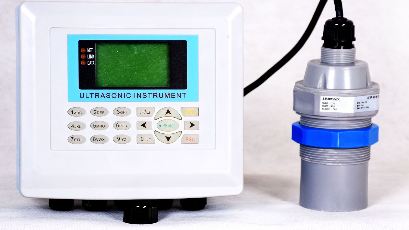
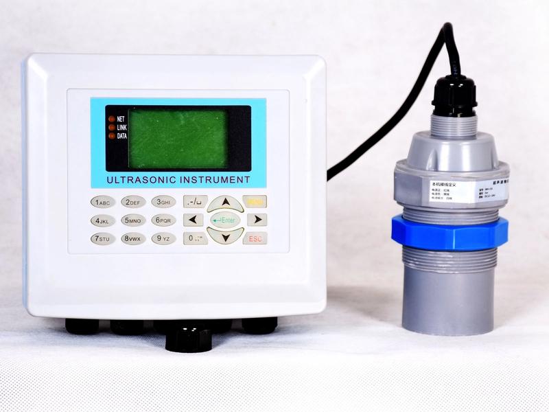
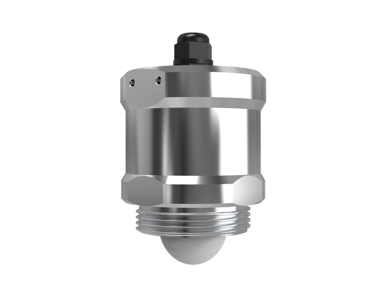
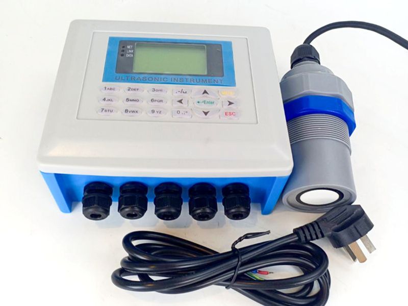
An ultrasonic level transmitter measures head by emitting a high-frequency acoustic pulse (typically 30–90 kHz) from a transducer aimed at the water surface, timing the round trip of the echo, and subtracting the measured distance from the known installation height to obtain the liquid level. The transducer is installed at a fixed elevation above the reference point of the primary element — the crest of a weir or the floor of a flume — so the distance reading becomes the head above that reference. Once the head is known, the transmitter applies the selected discharge equation and outputs instantaneous flow rate, totalized volume, and a 4–20 mA signal proportional to flow for the plant PLC or SCADA.
Because the transducer never touches the liquid, the system carries none of the fouling, corrosion, or pressure-loss penalties of inline devices, and it can be mounted above the channel without shutting down flow. For signal output, a loop-powered two-wire ultrasonic level transmitter delivers 4–20 mA directly into existing control loops, while a split ultrasonic level meter with remote display keeps the transducer at the channel and the display in the panel room — a common arrangement for flow stations where the electronics must be indoors.
The accuracy of the conversion rests on three things: the primary element (known geometry), the head measurement (ultrasonic repeatability of ±0.2–0.5% of range), and the installation. With the element correctly sized and the transducer correctly positioned, total system accuracy of ±1–2% of rate is realistic.
Mounting Requirements for the Ultrasonic Transducer
Where the transducer sits is as important as what it measures. The head measurement point is defined by the primary element standard — for a Parshall flume, two-thirds up the converging inlet; for a weir, a specified distance upstream of the crest. The transducer must sit directly above this point with a clear, unobstructed sound path to the water.
Three mounting rules dominate field practice. First, keep the transducer far enough from the element and from inlets so that turbulence and surface waves do not perturb the head reading; a minimum approach distance of several times the maximum head is typical, and a stilling well is often used to damp ripples. Second, stay outside the instrument's blanking distance (the near-field dead zone at the transducer face) and confirm the transmitter compensates for temperature, which shifts the speed of sound. Third, avoid aiming at foam, aerated zones, or broken, fast-moving water, all of which scatter the pulse. Where the flow is rough or the channel is deep and narrow, a stilling well or bypass well connected to the measurement point gives the most reliable reading.
Ultrasonic vs. Other Flow Measurement Methods
Level-based ultrasonic flow measurement is one of several technologies available to the water industry, and the choice is a trade-off between accuracy, cost, and the physical constraints of the site. The table below summarizes the most common options.
| Primary element / method | Discharge formula / principle | Best channel type | Typical accuracy | Head range |
|---|
| V-notch weir + ultrasonic | Q = C·h^2.5 | Low flows; clean water; pilot plants | ±1–2% of rate | 30–600 mm |
| Rectangular weir + ultrasonic | Q = C·h^1.5 | Medium flows; clean water | ±2–3% of rate | 30–750 mm |
| Parshall flume + ultrasonic | Q = C·h^1.55 | Solids-bearing water; wastewater | ±2–5% of rate | 60–800 mm |
| Palmer-Bowlus flume + ultrasonic | Q = C·h^n (n ≈ 1.5) | Partially filled circular sewers | ±2–5% of rate | 30–500 mm |
| Manning equation + ultrasonic | Q = (1/n)·A·R^(2/3)·S^(1/2) | Rectangular and natural channels | ±5–10% of rate | Depth-limited by channel |
| Doppler / area-velocity | Velocity × wetted area | Slurries; surcharged pipes | ±2–5% of rate | Full-pipe and open-channel |
| Electromagnetic (magnetic) meter | Induced voltage in full pipe | Clean or dirty liquid in full pipes | ±0.5–1% of rate | Full-pipe only |
Doppler and Area-Velocity Meters
Doppler meters measure flow by bouncing sound off entrained particles or bubbles and computing velocity from the Doppler shift, then multiplying by the wetted cross-section. They handle sludges, slurries, and surcharged lines where a weir or flume cannot be used, and they can be installed without modifying the channel. The trade-off is that accuracy depends on an assumed velocity profile, and the sensors require particles in the liquid — clean water defeats them. Typical accuracy is ±2–5% of rate.
Magnetic Flow Meters
Electromagnetic meters measure the voltage induced as a conductive liquid moves through a magnetic field, giving true average velocity, and are among the most accurate flow instruments available at ±0.5–1% of rate. But they are inline, full-pipe devices: the pipe must run full and the meter must stay wetted, which rules them out for gravity open channels. They are the natural choice for pump discharge lines and other closed full pipes, at a significantly higher cost per measuring point than a level-plus-primary-element station.
Radar and Hydrostatic Alternatives
Where ultrasonic is impractical — heavy foam, condensation, or very long range — a radar flow level meter for open water offers the same level-to-flow logic with microwave level measurement. Radar penetrates vapour and some foam better than ultrasonic, at a higher cost for equivalent duty. Where the surface is too disturbed for a reliable non-contact reading, a submersible hydrostatic level transmitter can sit in a stilling well and measure head by pressure, at the price of a wetted sensor that needs more maintenance. A full comparison of level technologies is available in our guide to water and wastewater level measurement sensor selection.
Limitations and How to Work Around Them
Level-based ultrasonic flow measurement is robust, but it has well-defined limits that engineers should design around.
Foam. Ultrasonic pulses are scattered and absorbed by foam, causing lost echoes or false readings. Light, stable foam can often be handled with a stilling well or a foam-cutting transducer frequency; heavy or moving foam may force a switch to radar or another technology.
Solids and debris. Weirs pond the upstream flow and settle grit; flumes self-clean but can still be blocked by large rags in sewer service. Regular inspection, and upstream sediment removal for weirs, belong in the maintenance plan.
Surcharge. If a flume or weir becomes submerged downstream — the flow backs up over the crest or through the throat — the free-flow discharge equation no longer holds and the indicated flow is wrong. The installation must allow free fall, or the station must switch to a submerged-flow calculation that needs a second level measurement.
Backwater effects. Downstream levels that rise into the measurement zone, tide-affected outfalls, or downstream obstructions all distort the head–discharge relationship. The primary element must be sized and placed so it operates in free-flow conditions across the entire expected range.
Low-head resolution. Because of the power-law relationship, the bottom of the head range is where small level errors produce the largest flow errors. Sizing the element so that normal flow sits in the upper two-thirds of the head range materially improves accuracy.
FAQ
How accurate is ultrasonic open channel flow measurement? With a properly installed primary element and transducer, total system accuracy is typically ±1–2% of rate for weirs and flumes, and ±5–10% for Manning-equation measurements on natural channels. The head reading itself is usually ±0.2–0.5% of range; most of the uncertainty comes from the structure's geometry and installation.
What is the difference between a weir and a flume? A weir is a plate that dams the flow and forces it over a crest, creating an upstream pond and head loss. A flume is a channel constriction that accelerates flow through a throat with little upstream ponding. Weirs are simpler and cheaper and suit clean, low flows; flumes pass sediment and debris more readily and are preferred in wastewater service.
Can ultrasonic flow measurement handle foam and rags in wastewater? Foam scatters the ultrasonic pulse, and rags can block a weir crest or a flume throat. Light foam is manageable with a stilling well, but heavy foam or debris-laden flow is better served by a Parshall or Palmer-Bowlus flume with routine inspection — or by switching to radar or area-velocity technology.
Do I need a stilling well? Not always, but it is recommended wherever the surface is wavy, turbulent, or aerated. A stilling well or bypass well connected to the head measurement point provides a calm, stable surface for the transducer, and it is nearly mandatory at high flows and at channels with strong inlet turbulence.
Can ultrasonic level flow measurement replace a magnetic flow meter? For open channels and gravity flows, yes — a magnetic meter cannot work because the pipe must run full. Where a full-pipe magnetic meter is applicable, it is more accurate (±0.5–1% of rate) but also more expensive. The decision comes down to whether the flow is in a full pipe or an open channel.
Get a Free Open-Channel Flow Package Recommendation
Sizing an open channel flow station means matching three things: the channel geometry (width, invert elevation, and available upstream length), the flow range (minimum, normal, and peak flow, plus the allowable head loss), and the liquid itself (clean water, stormwater, or wastewater with solids). Get those three right, and the rest — primary element type, transmitter model, stilling well design, and signal output — falls into place. WELK's engineers work with water and wastewater professionals daily and can recommend the right open-channel package from a range of more than 66 product models covering ultrasonic, radar, and hydrostatic level instrumentation for every duty. Send your channel dimensions and expected flow range to WELK for a free open-channel flow package recommendation, including primary element selection, transmitter specification, and mounting guidance — with factory-direct support from design through commissioning.