Technical
Ultrasonic Level Transmitter Blind Zone: Top 0.3 m Unmeasurable
Learn why ultrasonic level transmitters can't measure the top 0.2-0.3 m (blind zone) and how frequency affects it. Contact WELK for application support.
Learn why ultrasonic level transmitters can't measure the top 0.2-0.3 m (blind zone) and how frequency affects it. Contact WELK for application support.
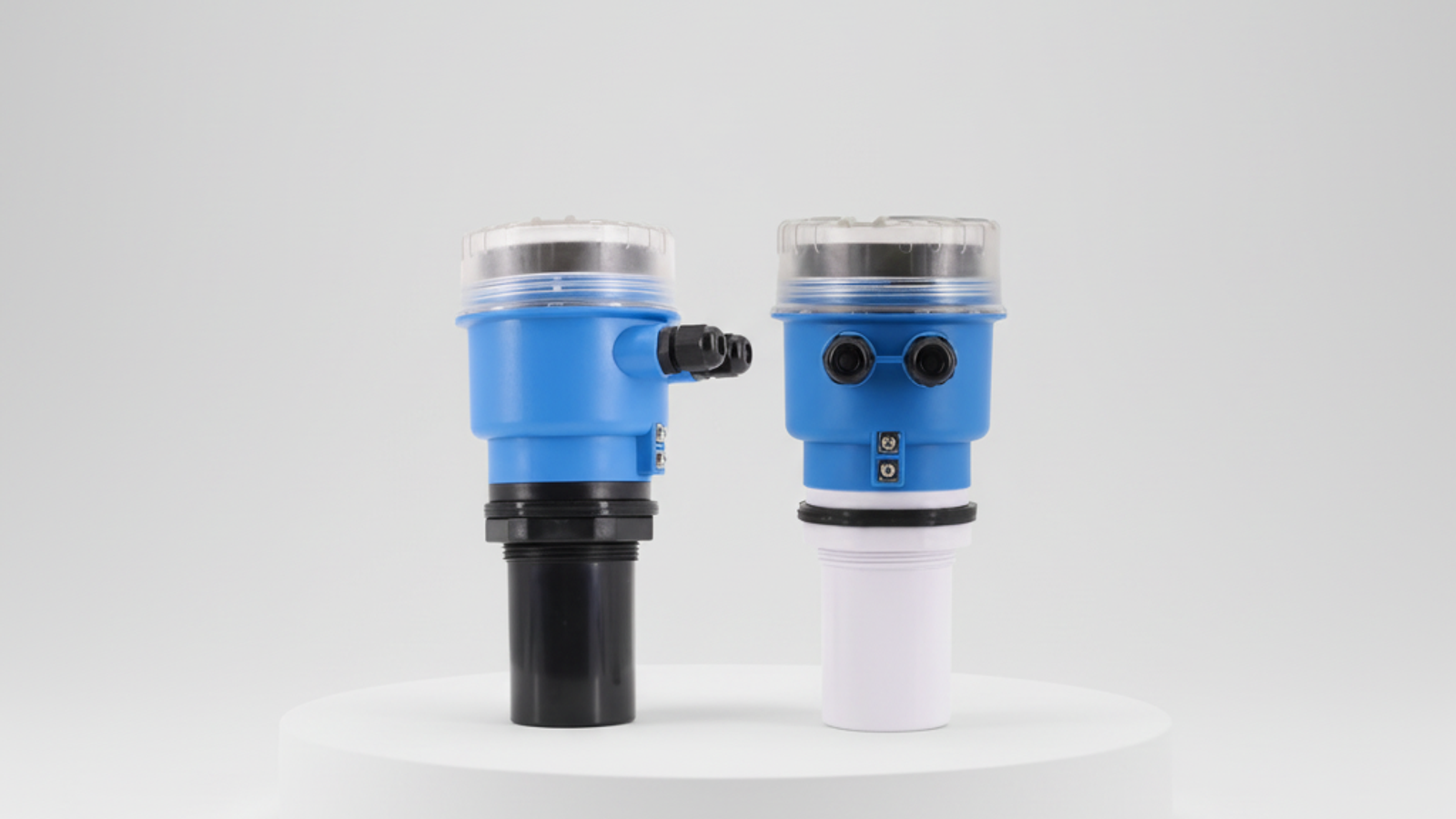
The blind zone of an ultrasonic level transmitter is the region immediately below the transducer face — typically the top 0.2–0.3 m of the tank — in which no reliable level reading can be obtained. It exists because the piezoelectric crystal inside the transducer keeps ringing for a short time (roughly 1–3 ms) after each transmit pulse, so the echo from a surface closer than that distance arrives while the instrument is still "deaf." The exact length depends on transducer frequency and rated range: a 10 m range sensor operating near 30 kHz typically has a blind zone of about 0.3–0.4 m, while a short-range, higher-frequency sensor can get down to 0.1–0.2 m.
Ultrasonic level measurement is a time-of-flight technique. The transducer fires a short burst of high-frequency sound — typically between 20 kHz and 70 kHz, above the human hearing range — down toward the liquid surface. The burst travels through the air above the liquid, reflects off the surface, and returns to the same transducer, which now acts as a receiver. The transmitter measures the round-trip time and converts it to distance.
Because the sound speed in air is known, the math is straightforward:
Distance = (speed of sound × round-trip time) / 2
At 20 °C, sound travels at roughly 343 m/s. If a pulse takes 29 ms to travel to the surface and back, the distance from the transducer to the liquid is about (343 × 0.029) / 2 ≈ 5.0 m. The level in the tank is then simply the tank height minus this distance.
This is the critical limitation that separates ultrasonic from radar. An ultrasonic transmitter measures the liquid level through the air — it needs a gas gap between the transducer and the surface. That is why the blind zone matters: the useful range always starts below the transducer face, and everything inside the blind zone is simply invisible to the instrument.
The speed of sound is not a constant. It rises roughly 0.6 m/s for every 1 °C increase in air temperature, and it is also affected by pressure and vapor composition. Modern ultrasonic transmitters correct for this with an integrated temperature sensor and a built-in speed-of-sound curve, which is why a good transmitter holds ±0.2%–0.5% of range accuracy across normal ambient conditions. But no compensation can help inside the blind zone — the instrument never gets an echo to measure there at all.
The blind zone is not a software setting that can simply be tuned to zero. It has three physical sources working together.
The heart of an ultrasonic transducer is a piezoelectric crystal. When a voltage is applied, the crystal deforms and vibrates, launching the sound pulse. When the voltage is removed, the crystal does not stop instantly — it keeps oscillating mechanically while the energy decays. This residual vibration, called ringing, typically lasts 1–3 ms depending on the crystal size, its resonant frequency, and the damping material behind it.
During this ringing period, the crystal is still physically moving. It cannot detect the faint returning echo, which arrives as a much smaller mechanical signal, because the echo is buried in the crystal's own decaying motion. The transducer is effectively deaf.
To manage this, the transmitter's electronics suppress or "blank" the receive signal during the ringing window. This electronic suppression is why the dead zone is often called the blanking distance or blocking distance in datasheets. The blanking window is deliberately set slightly longer than the physical ringing time, so the measured blind zone is always a little larger than the pure mechanical ringing length.
A third contributor is the acoustic near field. Directly in front of the transducer face, the sound waves from different parts of the crystal surface interfere with each other, producing an uneven, unpredictable sound field. Only beyond a certain distance does the beam settle into a stable, predictable cone. Echoes originating in this turbulent near-field region are unreliable even when the ringing has stopped.
You can see why 0.2–0.3 m is typical by doing the arithmetic. A 2 ms ringing time equals a round-trip distance of about 0.69 m of sound travel, which corresponds to a one-way distance of roughly 0.34 m from the transducer face. A 1.5 ms ringing time gives about 0.26 m. Combined with the near-field effect, the practical blanking distance for many standard transmitters lands in the 0.2–0.4 m band.
In the ultrasonic level literature, blind zone, dead zone, and blanking distance are used nearly interchangeably, which causes real confusion when you are comparing datasheets.
Some manufacturers add a distinction: the dead zone is the physical near-field region right at the transducer face, while the blanking distance is the larger, electronically enforced limit. In practice, the number on the datasheet is what matters — and it is the distance from the transducer face down to the nearest measurable level. If you are comparing two instruments, make sure you are comparing the same measurement point (from the transducer face, not from the nozzle flange). A 0.05 m difference in blind zone can translate into thousands of liters of unusable capacity on a large tank.
Put simply: the tank top is physically too close to the transducer for a clean echo to exist. In a typical installation, the transducer is mounted on a top nozzle, so the liquid surface near the top of the tank is only a fraction of a meter from the transducer face — exactly inside the ringing and near-field zone. Even if the electronics could hear an echo from that distance, the signal would be drowned out by the crystal's own decaying vibration and distorted by the irregular near-field beam.
There is no way to "wait longer" for this measurement — the instrument needs the surface to be below the blanking boundary before it can produce a valid reading. As a result, the top 0.2–0.3 m of the tank is structurally unmeasurable with a standard transducer, regardless of how good the electronics are.
The sound pulse does not travel as a narrow line; it spreads into a cone. For a typical transducer the full beam angle is in the range of 5°–12°, and the cone widens with distance. At 5 m from the face, a 6° cone is already about 0.5 m across. Any structure inside that cone — a ladder, a baffle, a heating coil, a pipe — creates a false echo, and the false echo problem is most severe near the transducer where the beam is densest. This is why mounting geometry and nozzle placement are inseparable from the blind-zone discussion.
Frequency is the single biggest factor determining the length of the blind zone, and it sets up a fundamental trade-off in ultrasonic level measurement.
A higher-frequency transducer, in the 40–70 kHz range, uses a smaller, faster-decaying crystal. Its ringing time is short, so the blind zone shrinks — often to 0.1–0.2 m. But high-frequency sound attenuates quickly in air, so these transducers are limited to shorter ranges, typically 2–8 m. They are the natural choice for small tanks, sumps, and applications where the usable range is limited anyway. This is the design philosophy behind WELK's low blind zone ultrasonic level sensor, which targets exactly this 0.1–0.2 m class of dead zone for short-range duties.
A lower-frequency transducer, in the 20–30 kHz range, uses a larger crystal that carries sound much farther through air — up to 10–15 m or more. The price is a longer ringing time and a correspondingly larger blind zone, typically 0.4–0.5 m. Large water reservoirs, deep wells, and tall chemical tanks need the range, so they must accept the longer blind zone. A two-wire ultrasonic level transmitter built for a 10 m span, for example, will typically quote a blind zone in the 0.3–0.4 m region.
Between the two extremes sit the compact ultrasonic level sensor and similar 40–50 kHz designs, which balance a 0.2–0.3 m blind zone against a 4–8 m range — the most common envelope for process tanks in water, chemical, and general industry applications. If your tank is 5 m tall, buying a 15 m range transmitter to "have margin" buys you nothing but a larger blind zone; matching the frequency to the actual tank height is the first rule of selecting for minimum dead zone.
When liquid rises into the blind zone, the ultrasonic transmitter loses the echo. The consequences depend on how the instrument is configured and how the level is used.
The most serious risk is overfill. If the transmitter is being used for high-level interlock or overfill protection, and the level rises into the blind zone, the instrument stops reading — it may hold a last valid value, report an error, or track a false echo from a tank structure instead of the liquid. Any of these outcomes can defeat the overfill protection at exactly the moment it is needed most. This is why the blanking distance must be treated as an upper limit of the measurable range, not an adjustable convenience. For safety-critical duties, consider a point level switch or a guided-wave alternative; many engineers also use the radar vs ultrasonic level meter comparison to decide which technology is right for a given tank.
The blind zone also costs real capacity. On a 3 m diameter tank, 0.3 m of unusable top space represents roughly 2.1 cubic meters — about 2,100 liters — of volume you can never safely fill while relying on the ultrasonic reading. Over a year of repeated batch fills, that is lost throughput. On large water and wastewater tanks, where the top few centimeters represent thousands of liters, choosing a low-blind-zone transducer can pay for itself quickly in recovered capacity.
As the surface enters the blind zone, the instrument often latches onto spurious echoes from the nozzle, the tank roof, or condensation on the transducer face. The result is a reading that is noisy, stuck, or jumping to a wrong value — behavior that operators routinely misinterpret as a transmitter fault when the real cause is the level simply being too high for the blind zone.
You cannot eliminate the blind zone, but you can engineer around it so that it costs you as little as possible.
If your tank is short — under about 6 m — there is no reason to carry a long-range transducer's dead zone. Specifying a low blind zone ultrasonic level sensor with a 0.1–0.2 m blanking distance can recover the top 10–20 cm of a small tank, which on a frequent-batch process is significant. Match the frequency to the tank height first, then check the blind-zone column on the datasheet before you commit.
A stilling well — a vertical pipe, typically 50–150 mm in diameter, open to the tank — confines the ultrasonic beam to a clean cylindrical path. It steadies the liquid surface, blocks foam, and eliminates most false echoes from internal structures. Inside a stilling well, the beam encounters a predictable surface and the effective performance at short range improves. Stilling wells are especially valuable in agitated tanks, in tanks with internal baffles, and for the external ultrasonic tank level gauge style of mounting where the instrument sits on a side connection. Keep the well clean and free of scale or condensation, which can mimic a level echo.
The nozzle is where most blind-zone problems are actually created. A tall, narrow nozzle puts the transducer face high above the tank, and the nozzle walls can ring and generate false echoes. Best practice:
The single most common procurement mistake is ordering a transmitter by maximum range alone. When you send an RFQ for an ultrasonic level meter, state the required usable span (from the lowest expected level to the highest), the tank height, the nozzle dimensions, and — explicitly — the maximum blind zone you can tolerate. A good supplier will use these numbers to recommend a frequency and model. If you ask WELK for a two-wire ultrasonic level transmitter or a split ultrasonic level meter with remote display for a tall tank, be ready to state the bottom-of-blank distance in the tank, not just the total height.
Every ultrasonic transmitter lets you configure the blanking distance within limits. Set it just above the physical minimum for your transducer — setting it higher than necessary wastes usable range, while setting it below the physical limit produces noise and false readings. The datasheet's minimum blanking value is the safe starting point.
The table below shows representative industry figures. Exact values vary by manufacturer and configuration — always verify the datasheet for the specific model and frequency.
| Model type | Typical frequency | Typical max range | Typical blind zone |
|---|---|---|---|
| Low blind zone sensor | 40–70 kHz | 2–6 m | 0.1–0.2 m |
| Compact ultrasonic sensor | 40–50 kHz | 4–8 m | 0.2–0.3 m |
| Two-wire ultrasonic transmitter | 30–40 kHz | 8–12 m | 0.3–0.4 m |
| Split ultrasonic meter (remote display) | 20–30 kHz | 10–15 m | 0.4–0.5 m |
Two patterns stand out. First, blind zone and maximum range grow together — you cannot have a 12 m range and a 0.1 m blind zone from a single ultrasonic transducer. Second, the split-configuration meters, which put the electronics in a remote display head to survive harsh process areas, use the same range/blind-zone relationship as integrated units; the split design affects wiring and maintenance, not the acoustic physics. You can browse the full ultrasonic level meters range to see how different frequencies and housing styles map onto these numbers.
Getting the most usable range out of any ultrasonic installation comes down to a handful of rules:
For a deeper look at whether ultrasonic is even the right choice for your service — especially with vapors, foam, or extreme temperatures — the radar vs ultrasonic level meter guide covers the decision in practical terms.
What is the blind zone of an ultrasonic level transmitter? The blind zone (also called dead zone or blanking distance) is the region directly below the transducer face — typically the top 0.2–0.3 m of the tank — where no reliable level reading is possible. It exists because the piezoelectric crystal keeps ringing for 1–3 ms after each pulse, during which the instrument cannot detect the returning echo.
Can the ultrasonic blind zone be reduced or eliminated? It cannot be eliminated, but it can be minimized. Higher-frequency transducers (40–70 kHz) have shorter ringing times and blind zones as small as 0.1–0.2 m, at the cost of shorter maximum range. Choosing a low-blind-zone sensor matched to your tank height is the most effective reduction.
What happens if the liquid level rises into the blind zone? The transmitter loses the true echo and may hold a stale value, report an error, or lock onto a false echo from the nozzle or tank structure. This can defeat overfill protection and cause erratic readings, so the high-level set point must always be kept below the blanking boundary.
How do I find the blind zone for a specific transmitter? Check the datasheet for "blind zone," "dead zone," or "blanking distance." Verify the measurement point (usually from the transducer face) and compare like-for-like across suppliers. For a given tank, also state the maximum acceptable blind zone in your RFQ so the supplier recommends the right frequency.
Does temperature affect the blind zone? Temperature affects the speed of sound and therefore the distance calculation, but it does not change the physical ringing time. The blind-zone length in meters stays essentially constant; temperature compensation corrects the measured distances, not the blanking distance.
The blind zone is physics — but how much it costs you is an engineering decision. A transducer frequency that matches your tank height, a low-blind-zone model where the top centimeters matter, a correctly sized stilling well, and an RFQ that states the required usable span will together recover most of that "unmeasurable" top space. The WELK team works with B2B buyers every day on exactly this problem: tell us your tank dimensions, your expected minimum and maximum levels, and your nozzle arrangement, and we will recommend a model — and a mounting plan — that keeps the dead zone out of your process. Contact WELK with your tank dimensions for application engineering support, or explore the full ultrasonic level meter range and the contact page to start the conversation.
Short-range ultrasonic level sensor for shallow tanks where the highest liquid level is close to the sensor face.
Compact ultrasonic level sensor for small tanks, utility vessels and OEM equipment with analog, digital or switch-output options.
Loop-powered ultrasonic level transmitter for simple 4-20 mA tank level signals in water, wastewater and compatible chemical applications.
Send drawings, dimensions, material, environment or operating conditions, and we will help confirm the right specification.
Uploaded reference files are included with the inquiry. For larger CAD packages, reply to the confirmation email or send them here:
Our team typically replies within 24 hours.